Power-On or Hibernate
Check for Valid Image
of On-chip flash
Check integrity of
existing image
Check if there exists a
new image
Boot the image
Wait-for-ever
Update the on-chip
Flash with new image
from serial Flash
Image Integrity
check phase
Image
program/update
phase
Image booting
phase
Y
Y
N
N
Failed Success
Failed
Success
Mass Erase
Flash Memory
CC3235SF Boot Flow
www.ti.com
778
SWRU543–January 2019
Submit Documentation Feedback
Copyright © 2019, Texas Instruments Incorporated
On-Chip Parallel Flash
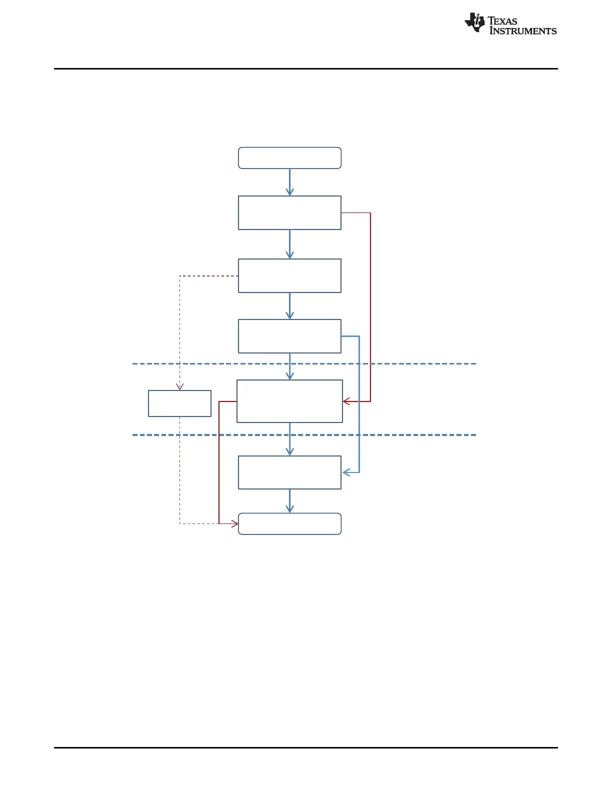
21.6 CC3235SF Boot Flow
Figure 21-10 shows a simplified boot flow of the CC3235SF microcontroller.
Figure 21-10. CC3235SF Boot Flow
21.7 Flash User Application and Memory Partition
The 1024-KB on-chip flash memory is split into two sections; the initial 2-KB section is the image header
that holds the image attributes. The header is automatically generated by the bootloader as part of
transferring the image from the serial flash to the on-chip flash.
The following 1022-KB section can be used by the user application image.
The header is auto-generated by the bootloader in all cases, except when the user will program a debug
image on to the serial flash. The debug image is handled as a special case, where the serial flash must be
formatted in development mode. In development mode, unlike production mode, the JTAG access is
granted to external debuggers.