ADC_MODULE Registers
www.ti.com
466
SWRU543–January 2019
Submit Documentation Feedback
Copyright © 2019, Texas Instruments Incorporated
Analog-to-Digital Converter (ADC)
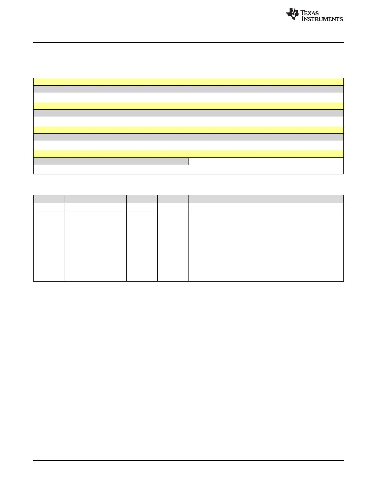
13.4.1.6 ADC_CH0_IRQ_STATUS Register (offset = 44h) [reset = 0h]
ADC_CH0_IRQ_STATUS is shown in Figure 13-8 and described in Table 13-8.
Figure 13-8. ADC_CH0_IRQ_STATUS Register
31 30 29 28 27 26 25 24
RESERVED
R-0h
23 22 21 20 19 18 17 16
RESERVED
R-0h
15 14 13 12 11 10 9 8
RESERVED
R-0h
7 6 5 4 3 2 1 0
RESERVED ADC_CHANNEL0_IRQ_STATUS
R-0h R/W-0h
Table 13-8. ADC_CH0_IRQ_STATUS Register Field Descriptions
Bit Field Type Reset Description
31-4 RESERVED R 0h
3-0 ADC_CHANNEL0_IRQ_S
TATUS
R/W 0h
Interrupt status register for ADC channel. Interrupt status can be
cleared on write.
Bit 3: when value 1 is written -> Clears FIFO overflow interrupt status
in the next cycle. If same interrupt is set in the same cycle, then the
interrupt would be set and the clear command ignored.
Bit 2: when value 1 is written -> Clears FIFO underflow interrupt
status in the next cycle.
Bit 1: when value 1 is written -> Clears FIFO empty interrupt status
in the next cycle.
Bit 0: when value 1 is written -> Clears FIFO full interrupt status in
the next cycle.