GPIO Registers
www.ti.com
164
SWRU543–January 2019
Submit Documentation Feedback
Copyright © 2019, Texas Instruments Incorporated
General-Purpose Input/Outputs (GPIOs)
5.5.3 GPIOIS Register (offset = 404h) [reset = 0h]
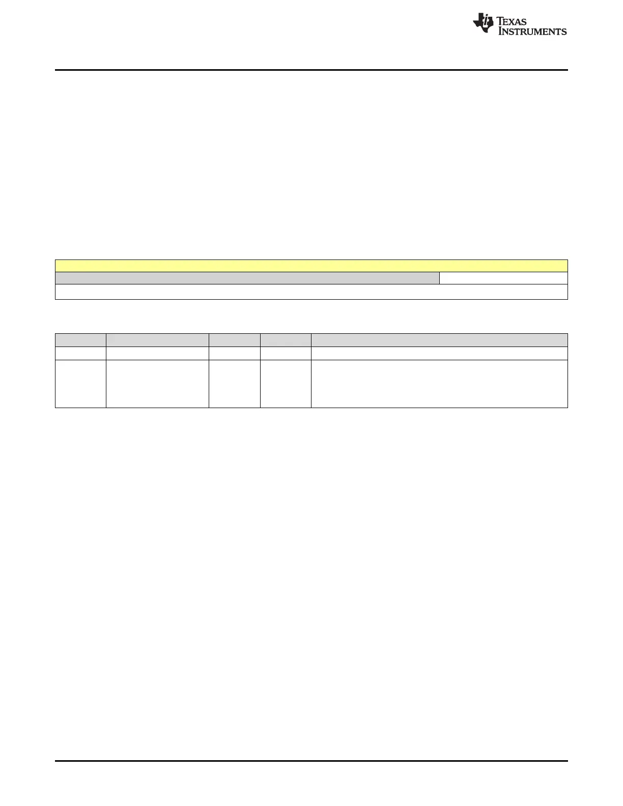
GPIOIS is shown in Figure 5-6 and described in Table 5-6 .
The GPIOIS register is the interrupt sense register. Setting a bit in the GPIOIS register configures the
corresponding pin to detect levels, while clearing a bit configures the corresponding pin to detect edges.
All bits are cleared by a reset.
To prevent false interrupts, the following steps should be taken when reconfiguring GPIO edge and
interrupt sense registers:
1. Mask the corresponding port by clearing the IME field in the GPIOIM register.
2. Configure the IS field in the GPIOIS register and the IBE field in the GPIOIBE register.
3. Clear the GPIORIS register.
4. Unmask the port by setting the IME field in the GPIOIM register.
Figure 5-6. GPIOIS Register
31 30 29 28 27 26 25 24 23 22 21 20 19 18 17 16 15 14 13 12 11 10 9 8 7 6 5 4 3 2 1 0
RESERVED IS
R-0h R/W-0h
Table 5-6. GPIOIS Register Field Descriptions
Bit Field Type Reset Description
31-8 RESERVED R 0h
7-0 IS R/W 0h
GPIO Interrupt Sense
0h = The edge on the corresponding pin is detected (edge-
sensitive).
1h = The level on the corresponding pin is detected (level-sensitive).





 To Next Page