Functional Description
www.ti.com
308
SWRU543–January 2019
Submit Documentation Feedback
Copyright © 2019, Texas Instruments Incorporated
General-Purpose Timers
The exact functionality of each GPTM is controlled by software and configured through the register
interface. Timer A and Timer B can be used individually, in which case they have a 16-bit counting range
for the 16/32-bit GPTM blocks. In addition, Timer A and Timer B can be concatenated to provide a 32-bit
counting range for the 16/32-bit GPTM blocks
NOTE: The prescaler can only be used when the timers are used individually.
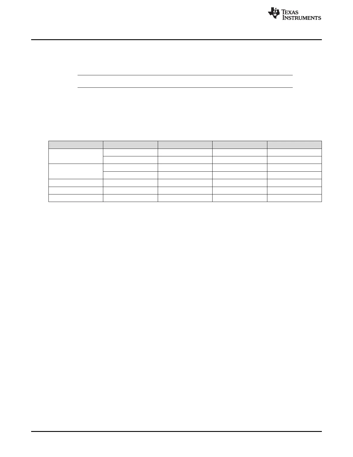
Table 9-2 lists the available modes for each GPTM block. When counting down in one-shot or periodic
modes, the prescaler acts as a true prescaler and contains the least significant bits (LSBs) of the count.
When counting up in one-shot or periodic modes, the prescaler acts as a timer extension, and holds the
most significant bits (MSBs) of the count. In input edge count, input edge time, and PWM mode, the
prescaler always acts as a timer extension, regardless of the count direction.
(1)
The prescaler is only available when the timers are used individually.
Table 9-2. General-Purpose Timer Capabilities
Mode Timer Use Count Direction Counter Size Prescaler Size
(1)
One-shot
Individual Up or down 16-bit 8-bit
Concatenated Up or down 32-bit –
Periodic
Individual Up or down 16-bit 8-bit
Concatenated Up or down 32-bit –
Edge count Individual Up or down 16-bit 8-bit
Edge time Individual Up or down 16-bit 8-bit
PWM Individual Down 16-bit 8-bit
Software configures the GPTM using the GPTM Configuration (GPTMCFG) register, the GPTM Timer A
Mode (GPTMTAMR) register, and the GPTM Timer B Mode (GPTMTBMR) register. When Timer A and
Timer B are in one of the concatenated modes, they can only operate in one mode. However, when
configured in an individual mode, Timer A and Timer B can be independently configured in any
combination of the individual modes.
9.3.1 GPTM Reset Conditions
After reset is applied to the GPTM module, the module is in an inactive state, and all control registers are
cleared and in their default states. Counters Timer A and Timer B are initialized to all 1s, along with their
corresponding registers:
• Load registers:
– GPTM Timer A Interval Load (GPTMTAILR) register
– GPTM Timer B Interval Load (GPTMTBILR) register
• Shadow registers:
– GPTM Timer A Value (GPTMTAV) register
– GPTM Timer B Value (GPTMTBV) register
The following prescale counters are initialized to all 0s:
• GPTM Timer A Prescale (GPTMTAPR) register
• GPTM Timer B Prescale (GPTMTBPR) register
• GPTM Timer A Prescale Snapshot (GPTMTAPS) register
• GPTM Timer B Prescale Snapshot (GPTMTBPS) register