Functional Description
www.ti.com
176
SWRU543–January 2019
Submit Documentation Feedback
Copyright © 2019, Texas Instruments Incorporated
Universal Asynchronous Receivers/Transmitters (UARTs)
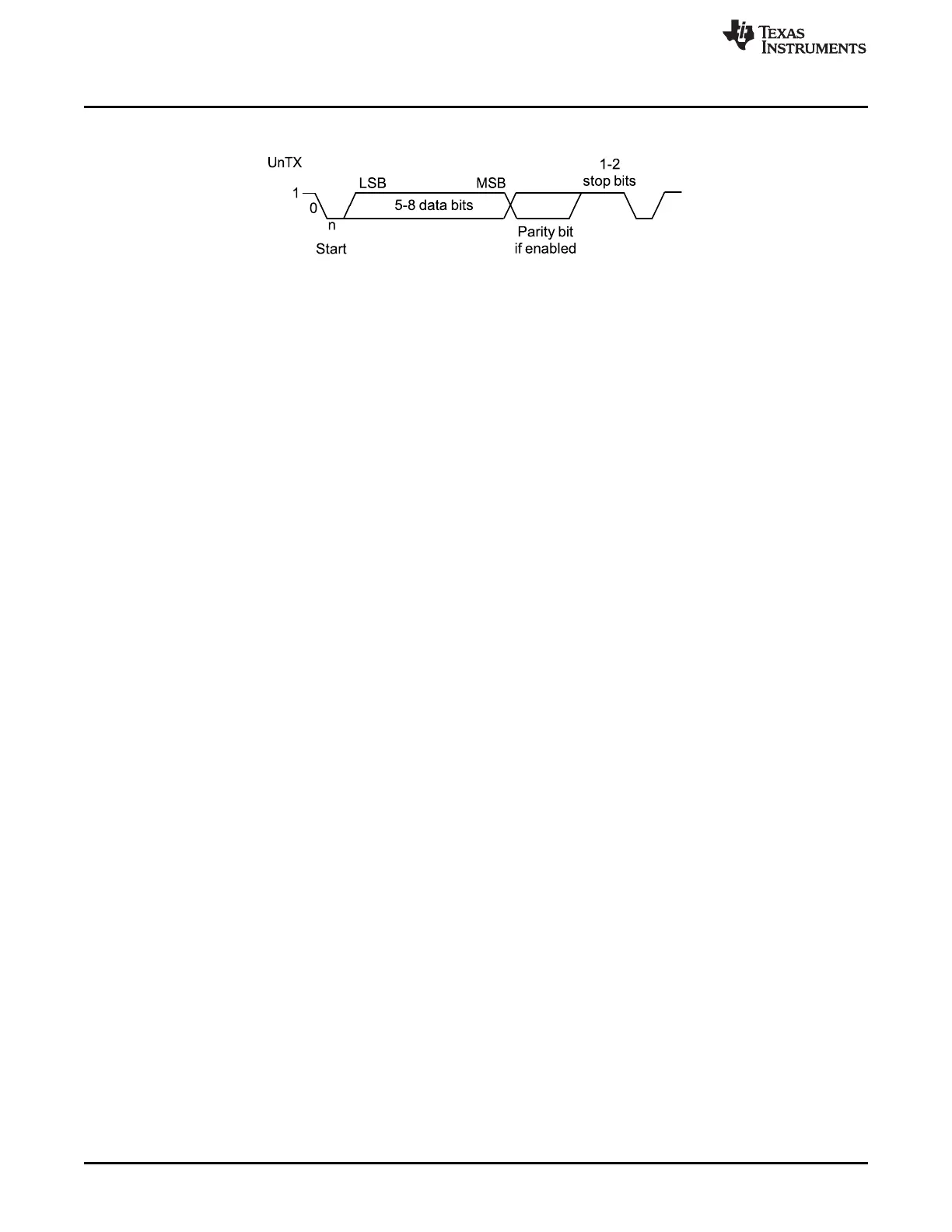
Figure 6-2. UART Character Frame
6.2.2 Baud-Rate Generation
The baud-rate divisor (BRD) is a 22-bit number consisting of a 16-bit integer and a 6-bit fractional part.
The number formed by these two values is used by the baud-rate generator to determine the bit period.
Having a fractional BRD allows the UART to generate all the standard baud rates.
The 16-bit integer is loaded through the UART Integer Baud-Rate Divisor (UARTIBRD) register and the 6-
bit fractional part is loaded with the UART Fractional Baud-Rate Divisor (UARTFBRD) register. The BRD
has the following relationship to the system clock (where BRDI is the integer part of the BRD and BRDF is
the fractional part, separated by a decimal place.)
BRD = BRDI + BRDF = UARTSysClk / (ClkDiv × Baud Rate) (1)
where UARTSysClk is the system clock connected to the UART, and ClkDiv is either 16 (if HSE in
UARTCTL is clear) or 8 (if HSE is set). By default, this is the main system clock described in
Section 15.3.5.
The 6-bit fractional number (loaded into the DIVFRAC bit field in the UARTFBRD register) can be
calculated by taking the fractional part of the BRD, multiplying it by 64, and adding 0.5 to account for
rounding errors:
UARTFBRD[DIVFRAC] = integer(BRDF × 64 + 0.5) (2)
The UART generates an internal baud-rate reference clock at 8× or 16× the baud-rate (referred to as
Baud8 and Baud16, depending on the setting of the HSE bit [bit 5] in UARTCTL). This reference clock is
divided by 8 or 16 to generate the transmit clock, and used for error detection during receive operations.
Along with the UART Line Control, High Byte (UARTLCRH) register, the UARTIBRD and UARTFBRD
registers form an internal 30-bit register. This internal register is only updated when a write operation to
UARTLCRH is performed, so any changes to the BRD must be followed by a write to the UARTLCRH
register for the changes to take effect. To update the baud-rate registers, there are four possible
sequences:
• UARTI BRD write, UARTF BRD write, and UARTLCRH write
• UARTF BRD write, UARTI BRD write, and UARTLCRH write
• UARTI BRD write and UARTLCRH write
• UARTF BRD write and UARTLCRH write
6.2.3 Data Transmission
Data received or transmitted is stored in two 16-byte FIFOs, though the RX FIFO has an extra 4 bits per
character for status information. For transmission, data are written into the TX FIFO. If the UART is
enabled, it causes a data frame to start transmitting with the parameters indicated in the UARTLCRH
register. Data continues to be transmitted until there is no data left in the TX FIFO. The BUSY bit in the
UART Flag (UARTFR) register is asserted when data are written to the TX FIFO (if the FIFO is nonempty)
and remains asserted while data are being transmitted. The BUSY bit is negated only when the TX FIFO
is empty, and the last character has been transmitted from the shift register, including the stop bits. The
UART can indicate that it is busy even though the UART may no longer be enabled.
When the receiver is idle (the UnRx signal is continuously 1), and the data input goes low (a start bit has
been received), the receive counter begins running and data are sampled on the eighth cycle of Baud16
or the fourth cycle of Baud8 depending on the setting of the HSE bit (bit 5) in UARTCTL.