www.ti.com
Functional Description
175
SWRU543–January 2019
Submit Documentation Feedback
Copyright © 2019, Texas Instruments Incorporated
Universal Asynchronous Receivers/Transmitters (UARTs)
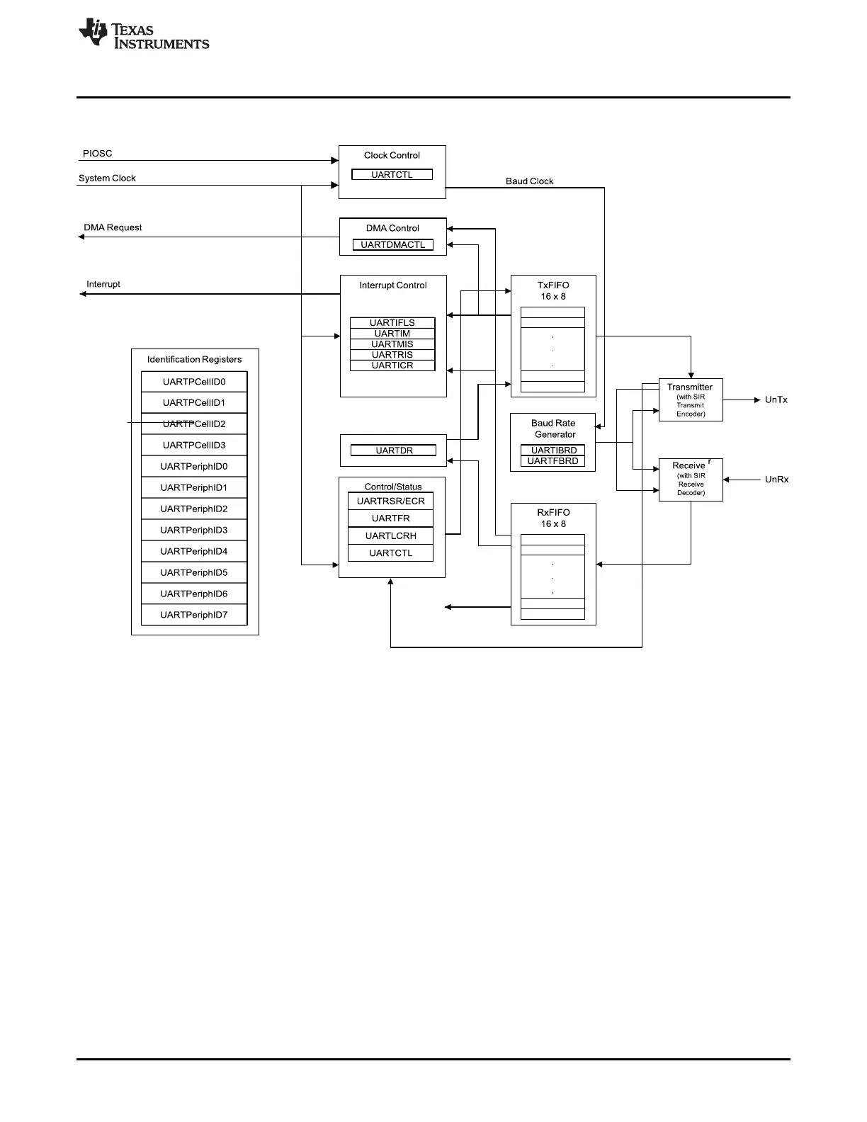
Figure 6-1. UART Module Block Diagram
6.2 Functional Description
Each CC32xx UART performs the functions of parallel-to-serial and serial-to-parallel conversions.
The UART is configured for transmit and receive through the TXE and RXE bits of the UART Control
(UARTCTL) register. Transmit and receive are both enabled out of reset. Before any control registers are
programmed, the UART must be disabled by clearing the UARTEN bit in the UARTCTL register. If the
UART is disabled during a TX or RX operation, the current transaction is completed before the UART
stops.
6.2.1 Transmit and Receive Logic
The transmit logic performs parallel-to-serial conversion on the data read from the TX FIFO. The control
logic outputs the serial bit stream, beginning with a start bit and followed by the data bits (LSB first), parity
bit, and the stop bits according to the programmed configuration in the control registers. See Figure 6-2 for
details.
The receive logic performs serial-to-parallel conversion on the received bit stream after a valid start pulse
has been detected. Overrun, parity, frame error checking, and line-break detection are also performed,
and their status accompanies the data written to the RX FIFO.