I2C Registers
www.ti.com
230
SWRU543–January 2019
Submit Documentation Feedback
Copyright © 2019, Texas Instruments Incorporated
Inter-Integrated Circuit (I
2
C) Interface
7.3.4 I2CMTPR Register (Offset = Ch) [reset = 1h]
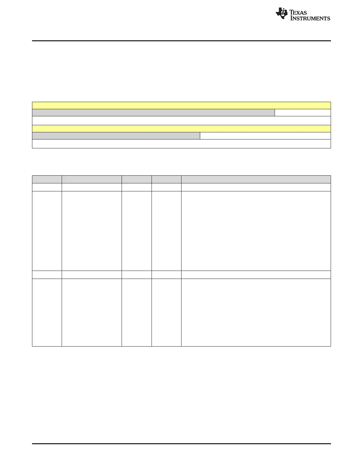
I2CMTPR is shown in Figure 7-17 and described in Table 7-8.
Return to Summary Table.
This register is programmed to set the timer period for the SCL clock and assign the SCL clock to
standard.
Figure 7-17. I2CMTPR Register
31 30 29 28 27 26 25 24 23 22 21 20 19 18 17 16
RESERVED PULSEL
R-0h R/W-0h
15 14 13 12 11 10 9 8 7 6 5 4 3 2 1 0
RESERVED TPR
R-0h R/W-1h
LEGEND: R/W = Read/Write; R = Read only; W1toCl = Write 1 to clear bit; -n = value after reset
Table 7-8. I2CMTPR Register Field Descriptions
Bit Field Type Reset Description
31-19 RESERVED R 0h
18-16 PULSEL R/W 0h
Glitch Suppression Pulse Width
This field controls the pulse width select for glitch suppression on the
SCL and SDA lines. The following values are the glitch suppression
values in terms of system clocks.
0h = Bypass
1h = 1 clock
2h = 2 clocks
3h = 3 clocks
4h = 4 clocks
5h = 8 clocks
6h = 16 clocks
7h = 31 clocks
15-7 RESERVED R 0h
6-0 TPR R/W 1h
Timer Period
This field is used in the equation to configure
SCL_PERIOD: SCL_PERIOD = 2 -(1 + TPR) -(SCL_LP + SCL_HP)
-CLK_PRD
where:
SCL_PRD is the SCL line period (I2C clock)
TPR is the Timer Period register value (range of 1 to 127)
SCL_LP is the SCL Low period (fixed at 6)
SCL_HP is the SCL High period (fixed at 4)
CLK_PRD is the system clock period in ns.





 To Next Page