Functional Description
www.ti.com
158
SWRU543–January 2019
Submit Documentation Feedback
Copyright © 2019, Texas Instruments Incorporated
General-Purpose Input/Outputs (GPIOs)
5.2.1 Data Control
The data direction register GPIODIR configures the GPIO as an input or an output, while the data register
GPIODATA either captures incoming data or drives it out to the pads.
5.2.1.1 Data Direction Operation
The GPIO Direction (GPIODIR) register configures each individual pin as an input or output. When the
data direction bit is cleared, the GPIO is configured as an input, and the corresponding data register bit
captures and stores the value on the GPIO port. When the data direction bit is set, the GPIO is configured
as an output, and the corresponding data register bit is driven out on the GPIO port.
5.2.1.2 Data Register Operation
To aid in the efficiency of software, the GPIO ports allow for the modification of individual bits in the GPIO
Data (GPIODATA) register by using bits [9:2] of the address bus as a mask. In this manner, software
drivers can modify individual GPIO pins in a single instruction without affecting the state of the other pins.
This method is more efficient than the conventional method of performing a read-modify-write operation to
set or clear an individual GPIO pin. To implement this feature, the GPIODATA register covers 256
locations in the memory map.
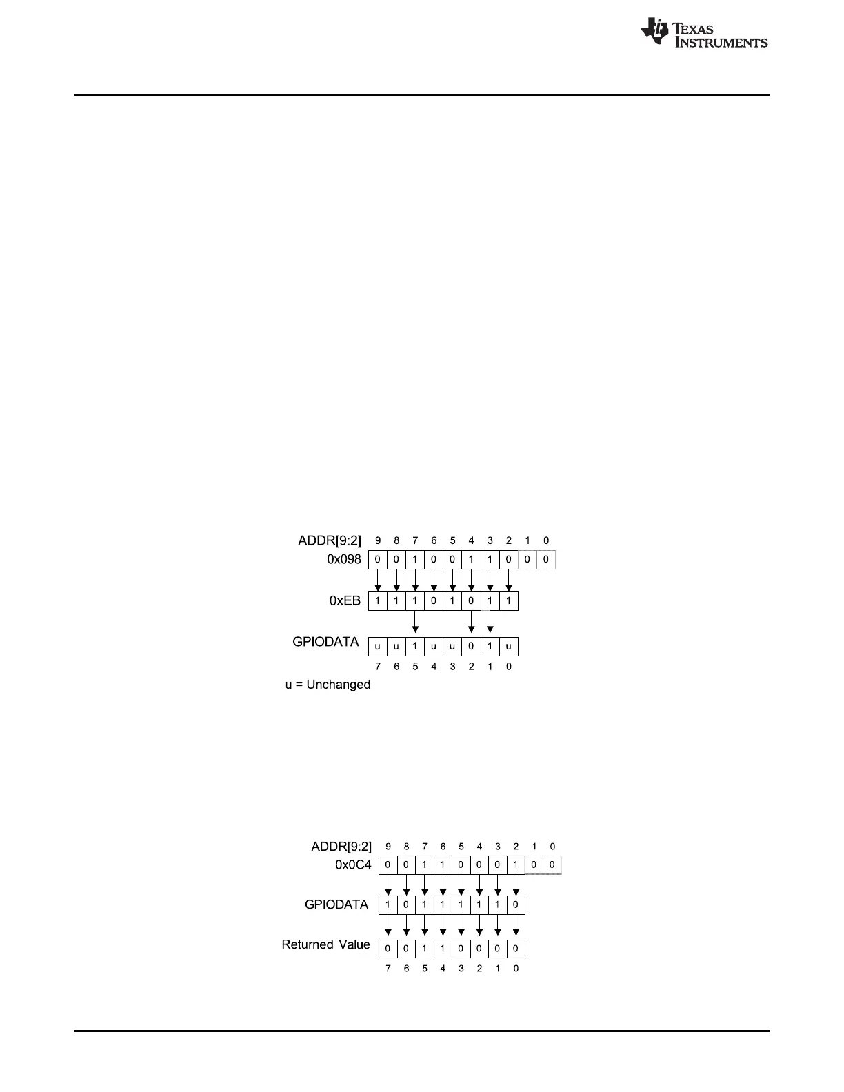
During a write, if the address bit associated with that data bit is set, the value of the GPIODATA register is
altered. If the address bit is cleared, the data bit is left unchanged. For example, writing a value of 0xEB to
the address GPIODATA + 0x098 has the results shown in Figure 5-2, where u indicates that data is
unchanged by the write. This example demonstrates how GPIODATA bits 5, 2, and 1 are written with a
single operation by using GPIODATA address alias 0x098 (offset address with regards to the base of the
respective GPIO instance A0 to A4).
Figure 5-2. GPIODATA Write Example
During a read, if the address bit associated with the data bit is set, the value is read. If the address bit
associated with the data bit is cleared, the data bit is read as 0, regardless of its actual value. For
example, reading address GPIODATA + 0x0C4 yields as shown in Figure 5-3. This example shows how to
read GPIODATA bits 5, 4, and 0 with a single operation by using GPIODATA address alias 0x0C4 (offset
address with regard to the base of the respective GPIO instance S0 to S4).
Figure 5-3. GPIODATA Read Example

 Loading...


