www.ti.com
Functional Description
311
SWRU543–January 2019
Submit Documentation Feedback
Copyright © 2019, Texas Instruments Incorporated
General-Purpose Timers
When software writes the TnEN bit in the GPTM Control (GPTMCTL) register, the timer is enabled for
event capture. Each input event on the CCP pin decrements or increments the counter by 1 until the event
count matches GPTMTnMATCHR and GPTMTnPMR. When the counts match, the GPTM asserts the
CnMRIS bit in the GPTM Raw Interrupt Status (GPTMRIS) register, and holds it until it is cleared by
writing the GPTM Interrupt Clear (GPTMICR) register. If the capture mode match interrupt is enabled in
the GPTM Interrupt Mask (GPTMIMR) register, the GPTM also sets the CnMMIS bit in the GPTM Masked
Interrupt Status (GPTMMIS) register. In up-count mode, the current count of the input events is held in
both the GPTMTnR and GPTMTnV registers. In down-count mode, the current count of the input events
can be obtained by subtracting the GPTMTnR or GPTMTnV from the value made up of the GPTMTnPR
and GPTMTnILR register combination.
The µDMA trigger is enabled by configuring and enabling the appropriate µDMA channel, as well as the
type of trigger enable in the GPTM DMA Event (GPTMDMAEV) register.
After the match value is reached in down-count mode, the counter is reloaded using the value in the
GPTMTnILR and GPTMTnPR registers, and then stopped because the GPTM automatically clears the
TnEN bit in the GPTMCTL register. Once the event count has been reached, all further events are ignored
until TnEN is re-enabled by software. In up-count mode, the timer is reloaded with 0x0 and continues
counting.
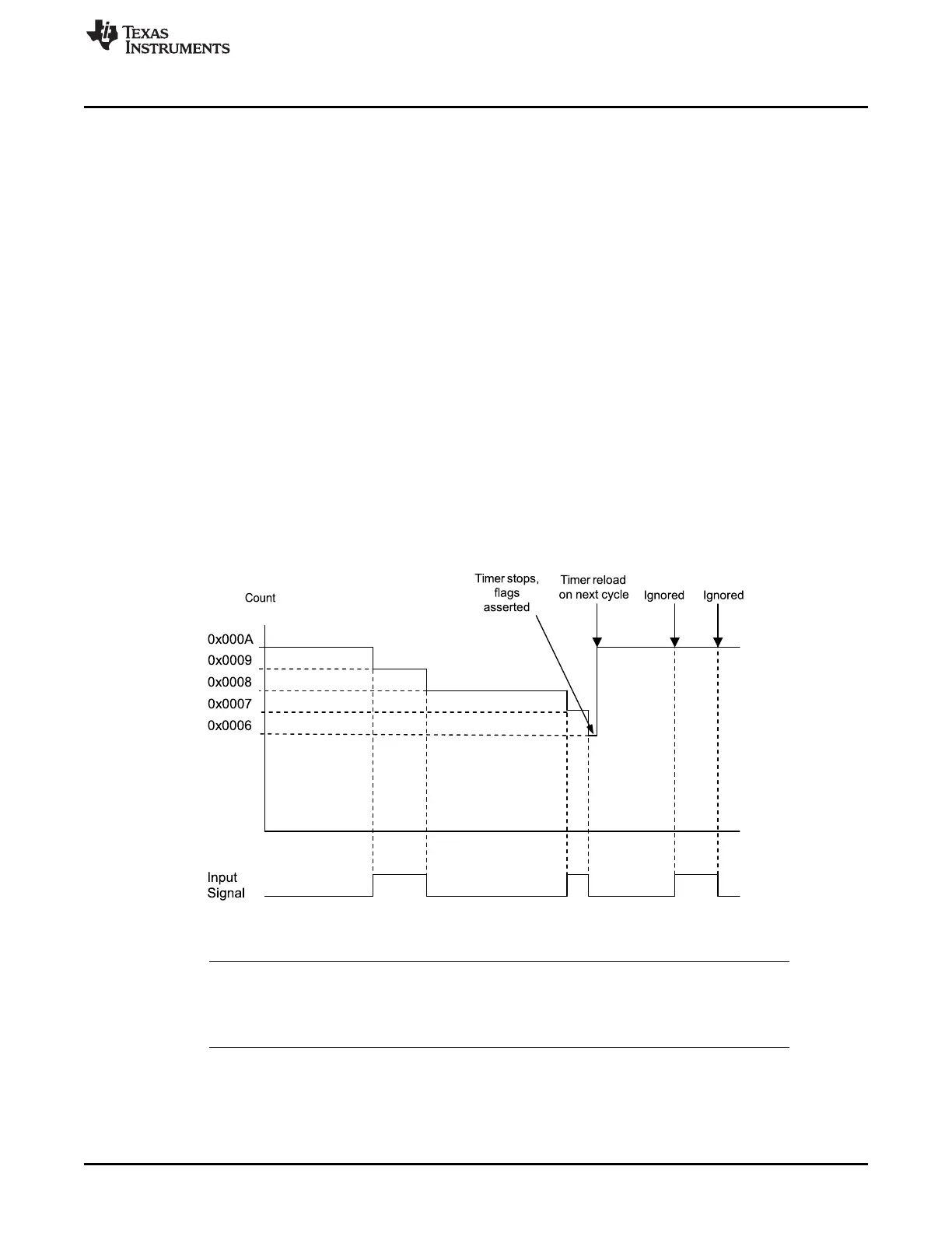
Figure 9-2 shows how input edge-count mode works. In this case, the timer start value is set to
GPTMTnILR = 0x000A, and the match value is set to GPTMTnMATCHR = 0x0006 so that four edge
events are counted. The counter is configured to detect both edges of the input signal.
The last two edges are not counted, because the timer automatically clears the TnEN bit after the current
count matches the value in the GPTMTnMATCHR register.
Figure 9-2. Input Edge-Count Mode Example, Counting Down
9.3.2.3 Input Edge-Time Mode
NOTE: For rising-edge detection, the input signal must be high for at least two system clock periods
following the rising edge. Similarly, for falling-edge detection, the input signal must be low for
at least two system clock periods following the falling edge. Based on this criteria, the
maximum input frequency for edge detection is 1/4 of the system frequency.





 To Next Page