Overview
www.ti.com
78
SWRU543–January 2019
Submit Documentation Feedback
Copyright © 2019, Texas Instruments Incorporated
Cortex
®
-M4 Peripherals
3.1 Overview
This chapter provides information on the CC32xx implementation of the Cortex
®
-M4 application processor
in CC32xx peripherals, including:
• SysTick (see Section 3.2.1) – Provides a simple, 24-bit clear-on-write, decrementing, wrap-on-zero
counter with a flexible control mechanism.
• Nested Vectored Interrupt Controller (NVIC) (see Section 3.2.2) – Facilitates low-latency exception and
interrupt handling, controls power management, and implements system control registers.
• System Control Block (SCB) (see Section 3.2.3) – Provides system implementation information and
system control, including configuration, control, and reporting of system exceptions.
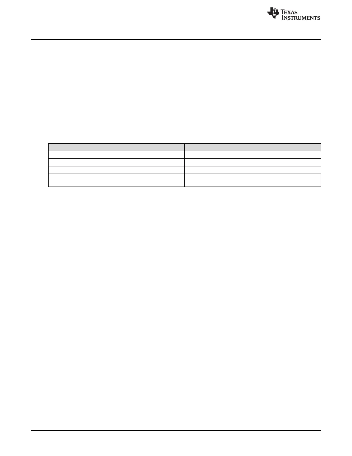
Table 3-1 shows the address map of the private peripheral bus (PPB). Some peripheral register regions
are split into two address regions, as indicated by two addresses listed.
Table 3-1. Core Peripheral Register Regions
Address Core Peripheral
0xE000.E010 to 0xE000.E01F System timer
0xE000.E100 to 0xE000.E4EF Nested vectored interrupt controller
0xE000.EF00 to 0xE000.EF03
0xE000.E008 to 0xE000.E00F
0xE000.ED00 to 0xE000.ED3F
System control block
3.2 Functional Description
This chapter provides information on the CC32xx implementation of the Cortex
®
-M4 application processor
in CC32xx peripherals: SysTick, NVIC, and SCB.
3.2.1 System Timer (SysTick)
SysTick is an integrated system timer which provides a simple, 24-bit clear-on-write, decrementing, wrap-
on-zero counter with a flexible control mechanism. The counter can be used in several different ways:
• An RTOS tick timer that fires at a programmable rate (for example, 100 Hz) and invokes a SysTick
routine
• A high-speed alarm timer using the system clock
• A variable rate alarm or signal timer – The duration is range-dependent on the reference clock used
and the dynamic range of the counter.
• A simple counter measuring time to completion and time used
• An internal clock source control based on missing or meeting durations. The COUNT bit in the
STCTRL control and status register can be used to determine if an action completed within a set
duration, as part of a dynamic clock management control loop.
When enabled, the timer counts down on each clock from the reload value to 0, reloads (wraps) to the
value in the STRELOAD register on the next clock edge, then decrements on subsequent clocks. Clearing
the STRELOAD register disables the counter on the next wrap. When the counter reaches 0, the COUNT
status bit is set. The COUNT bit clears on reads.
Writing to the STCURRENT register clears the register and the COUNT status bit. The write does not
trigger the SysTick exception logic. On a read, the current value is the value of the register at the time the
register is accessed.
The SysTick counter runs on the system clock. If this clock signal is stopped for low-power mode, the
SysTick counter stops. Ensure software uses aligned word accesses to access the SysTick registers.