Functional Description
www.ti.com
80
SWRU543–January 2019
Submit Documentation Feedback
Copyright © 2019, Texas Instruments Incorporated
Cortex
®
-M4 Peripherals
A pending interrupt remains pending until one of the following conditions occurs:
• The processor enters the ISR for the interrupt, changing the state of the interrupt from pending to
active. Then:
– For a level-sensitive interrupt, when the processor returns from the ISR, the NVIC samples the
interrupt signal. If the signal is asserted, the state of the interrupt changes to PENDING, which
might cause the processor to immediately re-enter the ISR. Otherwise, the state of the interrupt
changes to INACTIVE.
– For a pulse interrupt, the NVIC continues to monitor the interrupt signal, and if this is pulsed, the
state of the interrupt changes to PENDING and ACTIVE. In this case, when the processor returns
from the ISR the state of the interrupt changes to PENDING, which might cause the processor to
immediately re-enter the ISR.
If the interrupt signal is not pulsed while the processor is in the ISR, when the processor returns
from the ISR the state of the interrupt changes to INACTIVE.
• Software writes to the corresponding interrupt clear-pending register bit
– For a level-sensitive interrupt, if the interrupt signal is still asserted, the state of the interrupt does
not change. Otherwise, the state of the interrupt changes to INACTIVE.
– For a pulse interrupt, the state of the interrupt changes to INACTIVE if the state was PENDING, or
to ACTIVE if the state was ACTIVE and PENDING.
3.2.3 System Control Block (SCB)
The SCB provides system implementation information and system control, including configuration, control,
and reporting of the system exceptions.
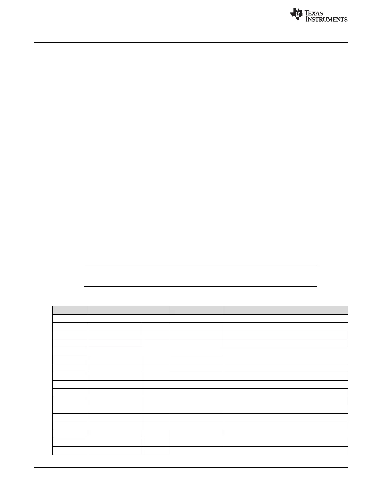
3.3 Register Map
Table 3-2 lists the Cortex
®
-M4 Peripheral SysTick, NVIC, and SCB registers. The offset listed is a
hexadecimal increment to the address of the register, relative to the core peripherals base address of
0xE000 E000.
NOTE: Register spaces that are not used are reserved for future or internal use. Software should
not modify any reserved memory address.
Table 3-2. Peripherals Register Map
Offset Name Type Reset Description
System Timer (SysTick) Registers
0x010 STCTRL R/W 0x0000.0000 SysTick Control and Status Register
0x014 STRELOAD R/W – SysTick Reload Value Register
0x018 STCURRENT R/WC – SysTick Current Value Register
Nested Vectored Interrupt Controller (NVIC) Registers
0x100 EN0 R/W 0x0000.0000 Interrupt 0 to 31 Set Enable
0x104 EN1 R/W 0x0000.0000 Interrupt 32 to 63 Set Enable
0x108 EN2 R/W 0x0000.0000 Interrupt 64 to 95 Set Enable
0x10C EN3 R/W 0x0000.0000 Interrupt 96 to 127 Set Enable
0x110 EN4 R/W 0x0000.0000 Interrupt 128 to 159 Set Enable
0x114 EN5 R/W 0x0000.0000 Interrupt 160 to 191 Set Enable
0x118 EN6 R/W 0x0000.0000 Interrupt 192 to 199 Set Enable
0x180 DIS0 R/W 0x0000.0000 Interrupt 0 to 31 Clear Enable
0x184 DIS1 R/W 0x0000.0000 Interrupt 32 to 63 Clear Enable
0x188 DIS2 R/W 0x0000.0000 Interrupt 64 to 95 Clear Enable
0x18C DIS3 R/W 0x0000.0000 Interrupt 96 to 127 Clear Enable
0x190 DIS4 R/W 0x0000.0000 Interrupt 128 to 159 Clear Enable