www.ti.com
Register Description
133
SWRU543–January 2019
Submit Documentation Feedback
Copyright © 2019, Texas Instruments Incorporated
Direct Memory Access (DMA)
4.3.4.1 DMA_STAT Register (offset = 0h) [reset = 0h]
Register mask: FFE0FFFFh
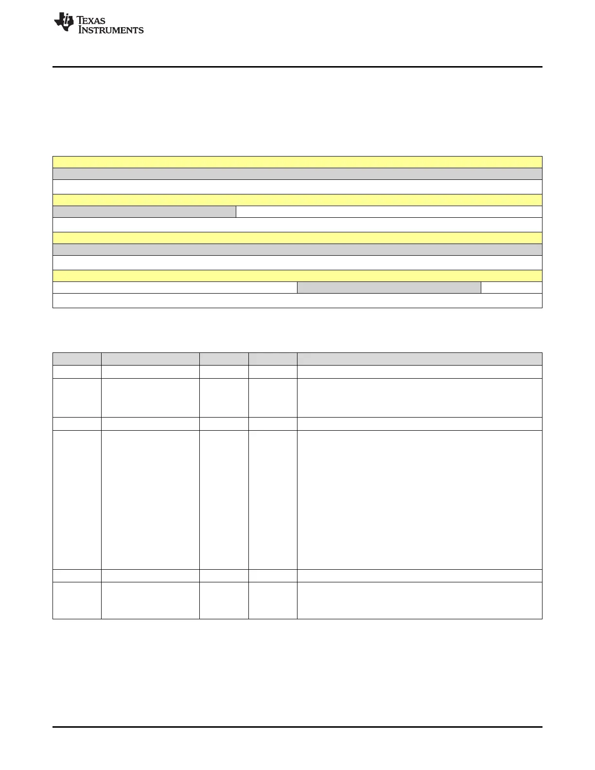
DMA_STAT is shown in Figure 4-7 and described in Table 4-11.
This register return the status of DMA controller.
Figure 4-7. DMA_STAT Register
31 30 29 28 27 26 25 24
RESERVED
R-0h
23 22 21 20 19 18 17 16
RESERVED DMACHANS
R-0h R-X
15 14 13 12 11 10 9 8
RESERVED
R-0h
7 6 5 4 3 2 1 0
STATE RESERVED MASTEN
R-0h R-0h R-0h
LEGEND: R/W = Read/Write; R = Read only; W1toCl = Write 1 to clear bit; -n = value after reset
Table 4-11. DMA_STAT Register Field Descriptions
Bit Field Type Reset Description
31-21 RESERVED R 0h
20-16 DMACHANS R X Available DMA channels minus 1.
This field contains a value equal to the number of DMA channels the
DMA controller is configured to use, minus one.
The value of 0x1F corresponds to 32 DMA channels.
15-8 RESERVED R 0h
7-4 STATE R 0h Control State Machine Status.
This field shows the current status of the control state machine.
Status can be one of the following 0xA-0xF undefined
0h = Idle
1h = Reading channel controller Data
2h = Reading source end pointer
3h = Reading destination end pointer
4h = Reading source data
5h = Writing destination data
6h = Waiting for DMA request to clear
7h = Writing channel controller data
8h = Stalled
9h = Done
3-1 RESERVED R 0h
0 MASTEN R 0h
Master enable status.
0h = DMA controller is disabled
1h = DMA controller is enabled





 To Next Page