I2C Registers
www.ti.com
224
SWRU543–January 2019
Submit Documentation Feedback
Copyright © 2019, Texas Instruments Incorporated
Inter-Integrated Circuit (I
2
C) Interface
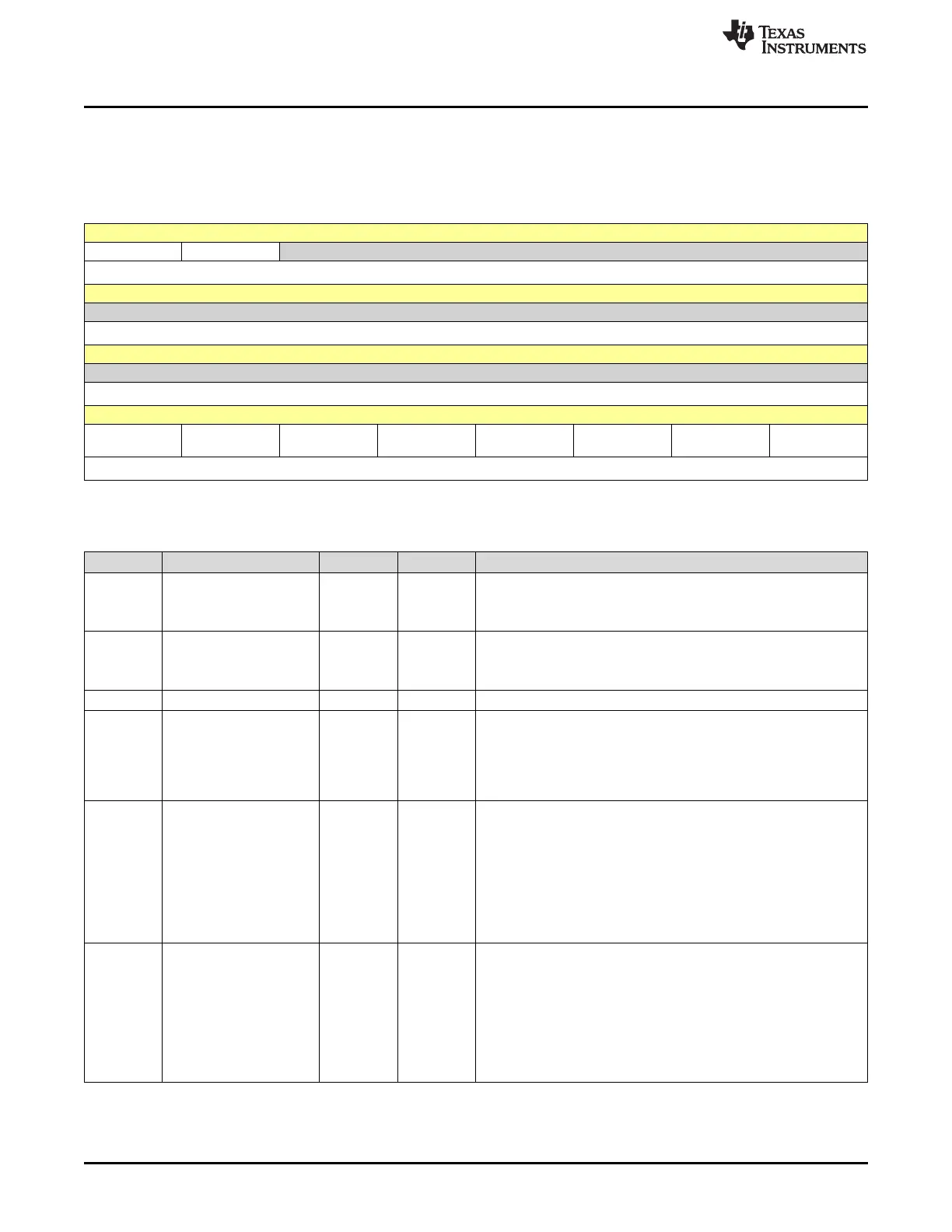
7.3.2 I2CMCS Register (Offset = 4h) [reset = 20h]
I2CMCS is shown in Figure 7-15 and described in Table 7-5.
Return to Summary Table.
Figure 7-15. I2CMCS Register
31 30 29 28 27 26 25 24
ACTDMARX ACTDMATX RESERVED
R/W-0h R-0h R-0h
23 22 21 20 19 18 17 16
RESERVED
R-0h
15 14 13 12 11 10 9 8
RESERVED
R-0h
7 6 5 4 3 2 1 0
CLKTO BUSBSY_OR_
BURST
IDLE_OR_QC
MD
ARBLST_OR_
HS
DATACK_OR_
ACK
ADRACK_OR_
STOP
ERROR_OR_S
TART
BUSY_OR_RU
N
R/W-0h R/W-0h R/W-1h R/W-0h R/W-0h R/W-0h R/W-0h R/W-0h
LEGEND: R/W = Read/Write; R = Read only; W1toCl = Write 1 to clear bit; -n = value after reset
Table 7-5. I2CMCS Register Field Descriptions
Bit Field Type Reset Description
31 ACTDMARX R/W 0h
DMA RX Active Status
0h (R) = DMA RX is not active
1h (R) = DMA RX is active
30 ACTDMATX R 0h
DMA TX Active Status
0h (R) = DMA TX is not active
1h (R) = DMA TX is active.
29-8 RESERVED R 0h
7 CLKTO R/W 0h
Clock Timeout Error
This bit is cleared when the master sends a STOP condition or if the
I2C master is reset.
0h (R) = No clock time-out error.
1h (R) = The clock time-out error has occurred.
6 BUSBSY_OR_BURST R/W 0h
Bus Busy (R) or Burst Enable (W)
The bit changes based on the START and STOP conditions.
0h (W) = Burst operation is disabled.
0h (R) = The I2C bus is idle.
1h (W) = The master is enabled to burst using the receive and
transmit FIFOs.
1h (R) = The I2C bus is busy.
Note that the BURST and RUN bits are mutually exclusive.
5 IDLE_OR_QCMD R/W 1h
I2C Idle (R) or Quick Command (W)
To execute a quick command, the START, STOP and RUN bits
must also be set. After the quick command is issued, the master
generates a STOP.
0h (W) = Bus transaction is not a quick command.
0h (R) = The I2C controller is not idle.
1h (W) = The bus transaction is a quick command.
1h (R) = The I2C controller is idle.





 To Next Page