Functional Description
www.ti.com
312
SWRU543–January 2019
Submit Documentation Feedback
Copyright © 2019, Texas Instruments Incorporated
General-Purpose Timers
In edge-time mode, the timer is configured as a 24-bit up counter or down counter, including the optional
prescaler with the upper timer value stored in the GPTMTnPR register and the lower bits in the
GPTMTnILR register. In this mode, the timer is initialized to the value loaded in the GPTMTnILR and
GPTMTnPR registers when counting down, and 0x0 when counting up. The timer can capture three types
of events: rising edge, falling edge, or both. The timer is placed into edge-time mode by setting the
TnCMR bit in the GPTMTnMR register, and the type of event that the timer captures is determined by the
TnEVENT fields of the GPTMCTL register. Table 9-6 lists the values loaded into the timer registers when
the timer is enabled.
Set the TRIGSEL bits of the GPTTRIGSEL register to detect GPIO triggers.
Table 9-6. Counter Values When the Timer is Enabled in Input Edge-Time Mode
Register Count-Down Mode Count-Up Mode
TnR GPTMTnILR 0x0
TnV GPTMTnILR 0x0
When software writes the TnEN bit in the GPTMCTL register, the timer is enabled for event capture. When
the selected input event is detected, the current timer counter value is captured in the GPTMTnR and
GPTMTnPS registers, and is available to be read by the microcontroller. The GPTM then asserts the
CnERIS bit in the GPTM Raw Interrupt Status (GPTMRIS) register, and holds it until it is cleared by writing
the GPTM Interrupt Clear (GPTMICR) register. If the capture mode event interrupt is enabled in the GPTM
Interrupt Mask (GPTMIMR) register, the GPTM also sets the CnEMIS bit in the GPTM Masked Interrupt
Status (GPTMMIS) register. In this mode, the GPTMTnR and GPTMTnPS registers hold the time at which
the selected input event occurred, while the GPTMTnV register holds the free-running timer value. These
registers can be read to determine the time that elapsed between the interrupt assertion and the entry into
the ISR.
In addition to generating interrupts, a µDMA trigger can be generated. The µDMA trigger is enabled by
configuring the appropriate µDMA channel, as well as the type of trigger selected in the GPTM DMA Event
(GPTMDMAEV) register.
After an event is captured, the timer does not stop counting. It continues to count until the TnEN bit is
cleared. When the timer reaches the time-out value, it is reloaded with 0x0 in up-count mode, and the
value from the GPTMTnILR and GPTMTnPR registers in down-count mode.
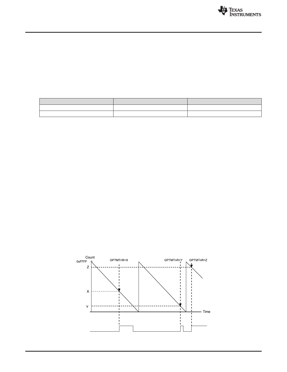
Figure 9-3 shows how input edge-timing mode works. In the diagram, the start value of the timer is the
default value of 0xFFFF, and the timer is configured to capture rising-edge events.
Each time a rising edge event is detected, the current count value is loaded into the GPTMTnR and
GPTMTnPS registers, and is held there until another rising-edge is detected (at which point the new count
value is loaded into the GPTMTnR and GPTMTnPS registers).
Figure 9-3. 16-Bit Input Edge-Time Mode Example





 To Next Page