WDTCTL
WDTICR
WDTRIS
WDTMIS
WDTLOCK
WDTTEST
WDTPeriphID0
WDTPeriphID1
WDTPeriphID2
WDTPeriphID3
WDTPeriphID4
WDTPeriphID5
WDTPeriphID6
WDTPeriphID7
Control / Clock /
Interrupt
Generation
WDTLOAD
Interrupt
System Clock
32-Bit Down
Counter
0x0000.0000
Comparator
WDTVALUE
Identification Registers
WDTPCellID0
WDTPCellID1
WDTPCellID2
WDTPCellID3
Overview
www.ti.com
348
SWRU543–January 2019
Submit Documentation Feedback
Copyright © 2019, Texas Instruments Incorporated
Watchdog Timer
10.1 Overview
The watchdog timer (WDT) in the CC32xx device generates a regular interrupt or a reset when a time-out
value is reached. The WDT regains control when a system fails because of a software error or because
an external device fails to respond in the expected way. The CC32xx has one WDT module, clocked by
the system clock.
The WDT module supports the following features:
• A 32-bit down counter with a programmable load register
• Lock register protection from runaway software
• Reset generation cannot be disabled
• User-enabled stalling when the microcontroller asserts the CPU Halt flag during debug
The WDT can be configured to generate an interrupt to the controller on its first time-out, and a reset
signal on its second time-out. When the WDT is configured, the Watchdog Timer Lock (WDTLOCK)
register is written to prevent software from inadvertent altering the timer configuration.
The WDT module supports the following clock source: system clock (80 MHz in run mode)
The clock used for WDT is selected by the configuration register APRCM:WDTCLKEN.
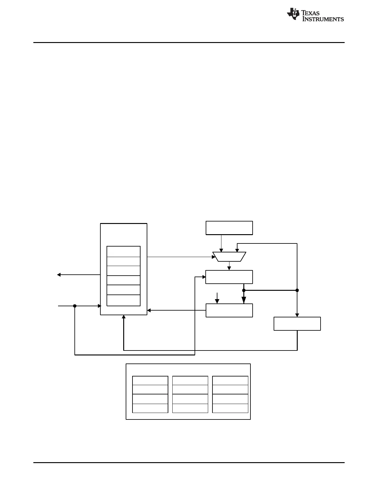
10.1.1 Block Diagram
Figure 10-1 shows the WDT module block diagram.
Figure 10-1. WDT Module Block Diagram