www.ti.com
Functional Description
177
SWRU543–January 2019
Submit Documentation Feedback
Copyright © 2019, Texas Instruments Incorporated
Universal Asynchronous Receivers/Transmitters (UARTs)
The start bit is valid and recognized if the UnRx signal is still low on the eighth cycle of Baud16 (HSE
clear) or the fourth cycle of Baud8 (HSE set), otherwise it is ignored. After a valid start bit is detected,
successive data bits are sampled on every 16th cycle of Baud16 or 8th cycle of Baud8 (that is, 1 bit period
later) according to the programmed length of the data characters and value of the HSE bit in UARTCTL.
The parity bit is then checked if parity mode is enabled. Data length and parity are defined in the
UARTLCRH register.
Lastly, a valid stop bit is confirmed if the UnRx signal is high, otherwise a framing error has occurred.
When a full word is received, the data are stored in the RX FIFO along with any error bits associated with
that word.
6.2.3.1 Flow Control
Flow control can be accomplished by either hardware or software. The following sections describe the
different methods.
6.2.3.1.1 Hardware Flow Control (RTS/CTS)
Hardware flow control between two devices is accomplished by connecting the U1RTS output to the clear-
to-send input on the receiving device, and connecting the request-to-send output on the receiving device
to the U1RTS input.
The U1RTS input controls the transmitter. The transmitter may only transmit data when the U1RTS input
is asserted. The U1RTS output signal indicates the state of the RX FIFO. U1CTS remains asserted until
the preprogrammed watermark level is reached, indicating that the RX FIFO has no space to store
additional characters.
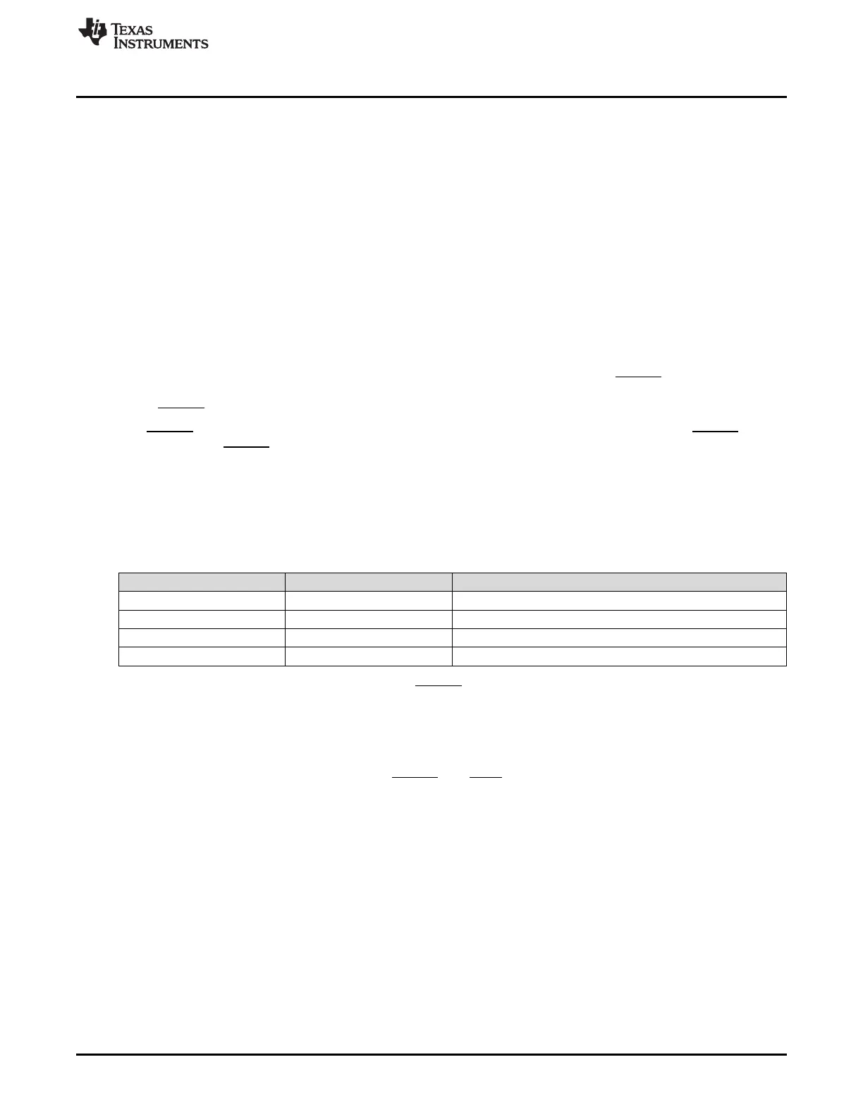
The UARTCTL register bits 15 (CTSEN) and 14 (RTSEN) specify the flow control mode as shown in
Table 6-1.
Table 6-1. Flow Control Mode
CTSEN RTSEN Description
1 1 RTS and CTS flow control enabled
1 0 Only CTS flow control enabled
0 1 Only RTS flow control enabled
0 0 RTS and CTS flow control disabled
When RTSEN is 1, software cannot modify the U1RTS output value through the UARTCTL register
request-to-send (RTS) bit, and the status of the RTS bit should be ignored.
6.2.3.1.2 Software Flow Control (Modem Status Interrupts)
Software flow control between two devices is accomplished by using interrupts to indicate the status of the
UART. Interrupts may be generated for the U1CTS and U1RI signals using bit 1 of the UARTIM register.
The raw and masked interrupt status may be checked using the UARTRIS and UARTMIS registers,
respectively. These interrupts may be cleared using the UARTICR register.
6.2.3.2 FIFO Operation
The UART has two 16 × 8 FIFOs; one for transmit and one for receive. Both FIFOs are accessed through
the UART Data (UARTDR) register. Read operations of the UARTDR register return a 12-bit value
consisting of 8 data bits and 4 error flags, while write operations place 8-bit data in the TX FIFO.
Out of reset, both FIFOs are disabled and act as 1-byte-deep holding registers. The FIFOs are enabled by
setting the FEN bit in UARTLCRH.
FIFO status can be monitored through the UART Flag (UARTFR) register and the UART Receive Status
(UARTRSR) register. Hardware monitors empty, full, and overrun conditions. The UARTFR register
contains empty and full flags (TXFE, TXFF, RXFE, and RXFF bits), and the UARTRSR register shows
overrun status through the OE bit. If the FIFOs are disabled, the empty and full flags are set according to
the status of the 1-byte-deep holding registers.





 To Next Page