www.ti.com
Overview
157
SWRU543–January 2019
Submit Documentation Feedback
Copyright © 2019, Texas Instruments Incorporated
General-Purpose Input/Outputs (GPIOs)
5.1 Overview
This chapter describes the general-purpose input/output (GPIO) module and the I/O pad cells in the
CC32xx.
The GPIO module is composed of four physical GPIO blocks, each corresponding to an individual GPIO
port (Port 0, Port A1, Port A2, Port A3). The GPIO module supports up to 32 programmable I/O pins when
the GPIO function is selected in I/O pin multiplexing.
The GPIO module has the following features:
• Up to 26 GPIOs depending on pin multiplexing configuration, excluding the two SWD pins (TMS, TCK)
and the two pins dedicated for antenna switch control (diversity selection):
– 2-wire debug corresponds to the SOP mode (sense-on-power).
– If 4-wire JTAG mode is used instead (by pulling the sense-on-power pin 2:0 to 000 using board-
level pulldown resistors), then the number of digital I/Os, excluding JTAG and antenna diversity
controls, is 24.
• Programmable control for GPIO interrupts:
– Interrupt generation masking
– Edge-triggered on rising, falling, or both
– Level-sensitive on high or low values
5.2 Functional Description
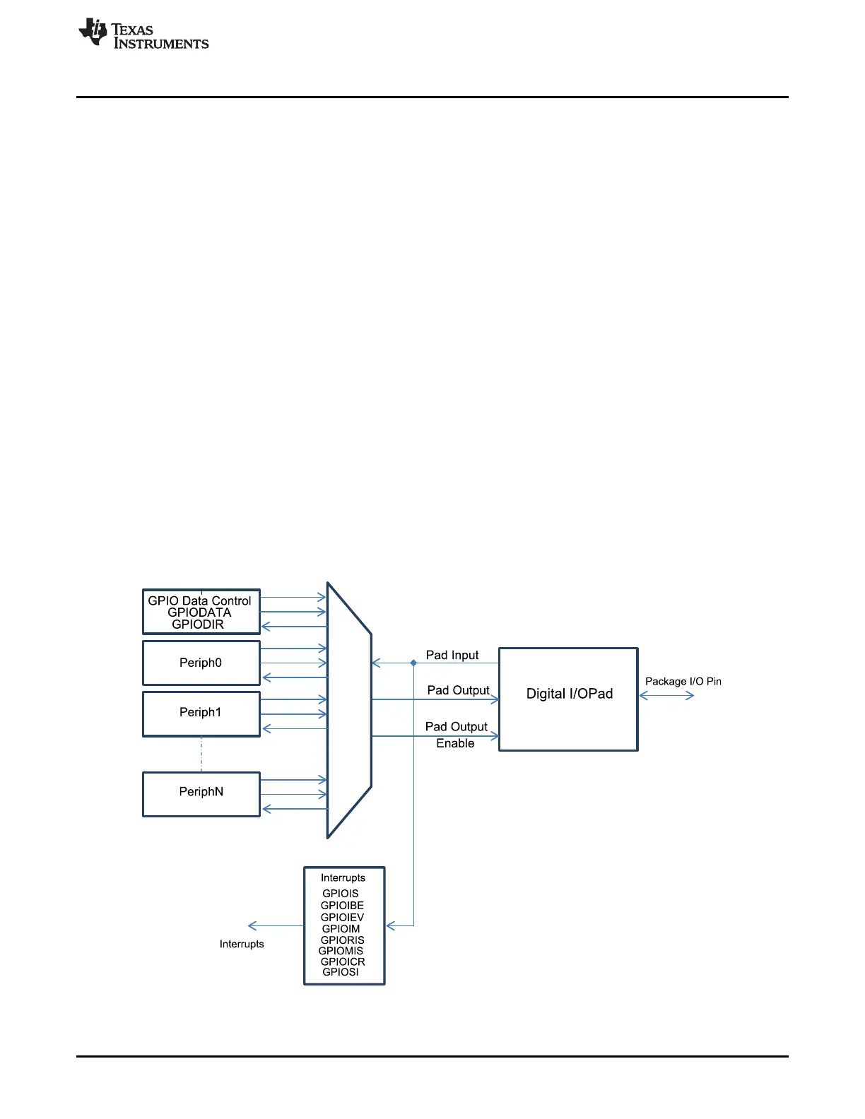
Each GPIO port is a separate hardware instance of the same physical block. The CC32xx microcontroller
contains four ports and thus four of these physical GPIO blocks. Each GPIO block has 8 bits. The
available GPIOs are a subset of these 32 GPIO signals. For details on the usable GPIOs, refer to
Table 16-6.
Figure 5-1. Digital I/O Pads