Register Description
www.ti.com
146
SWRU543–January 2019
Submit Documentation Feedback
Copyright © 2019, Texas Instruments Incorporated
Direct Memory Access (DMA)
4.3.4.14 DMA_ALTCLR Register (offset = 34h) [reset = 0h]
DMA_ALTCLR is shown in Figure 4-20 and described in Table 4-24.
Each bit of this register represents the corresponding DMA channel. Setting a bit clears the corresponding
SET[n] bit in the DMAALTSET register. For Ping-Pong and Scatter-Gather cycle types, the DMA controller
automatically sets these bits to select the alternate channel control data structure.
Figure 4-20. DMA_ALTCLR Register
31 30 29 28 27 26 25 24 23 22 21 20 19 18 17 16 15 14 13 12 11 10 9 8 7 6 5 4 3 2 1 0
CLR_n
W-0h
LEGEND: R/W = Read/Write; R = Read only; W1toCl = Write 1 to clear bit; -n = value after reset
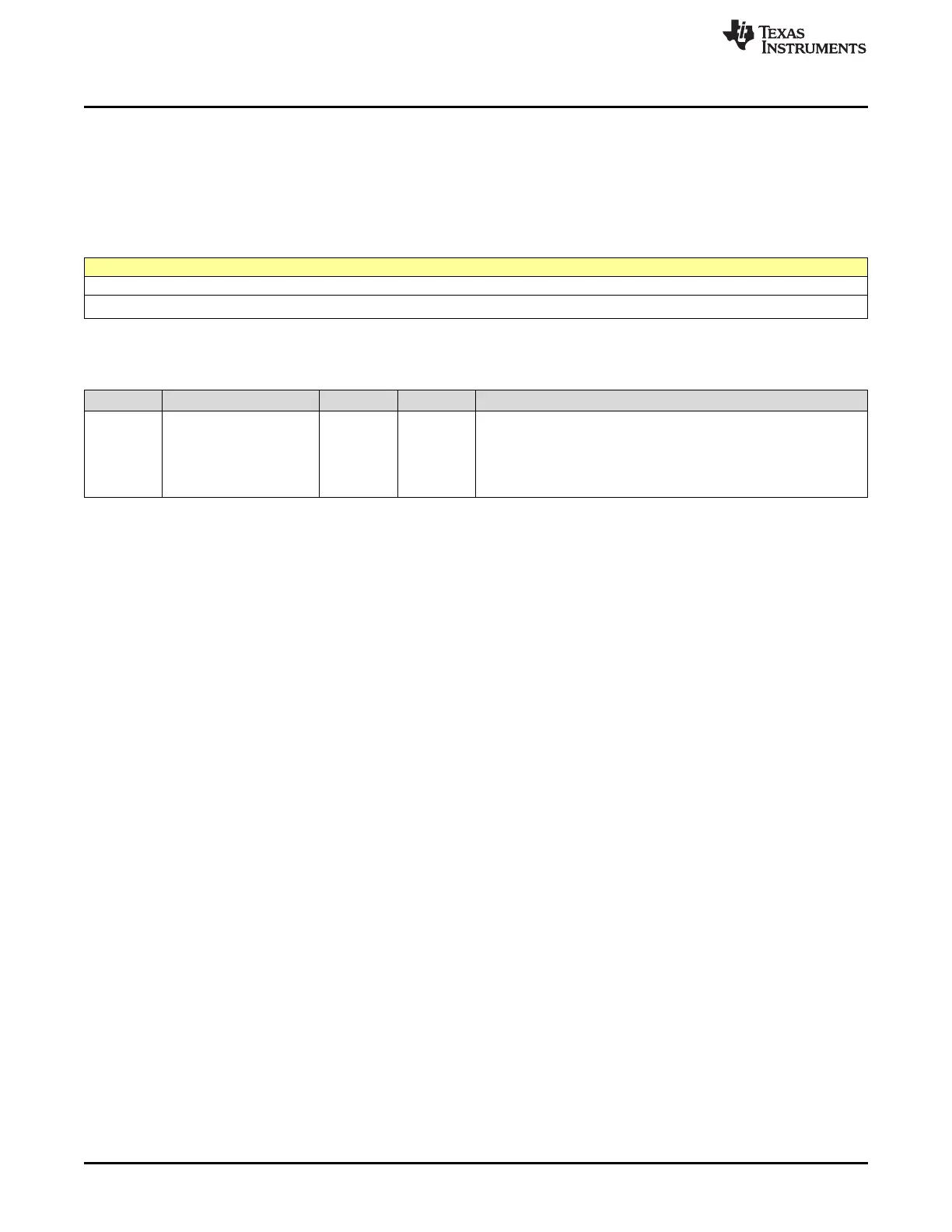
Table 4-24. DMA_ALTCLR Register Field Descriptions
Bit Field Type Reset Description
31-0 CLR_n W 0h
Channel [n] Alternate Clear
0h = No effect
1h = Setting a bit clears the corresponding SET[n] bit in the
DMAALTSET register meaning that channel [n] is using the primary
control structure

 Loading...


