www.ti.com
Module Initialization
283
SWRU543–January 2019
Submit Documentation Feedback
Copyright © 2019, Texas Instruments Incorporated
SPI (Serial Peripheral Interface)
The SPI supports only one SPI word per register (receiver or transmitter) and does not support successive
8-bit or 16-bit accesses for a single SPI word. The SPI word received is always right-justified on the LSB
of the 32-bit SPI_RX register, and the SPI word to transmit is always right-justified on the LSB of the 32-bit
SPI_TX register. The bits above SPI word length are ignored, and the content of the data registers is not
reset between the SPI data transfers. The user is responsible for the coherence between the number of
bits of the SPI word, the number of bits of the access, and the enabled byte. Only aligned accesses are
supported. In master mode, data must not be written in the transmit register when the channel is disabled.
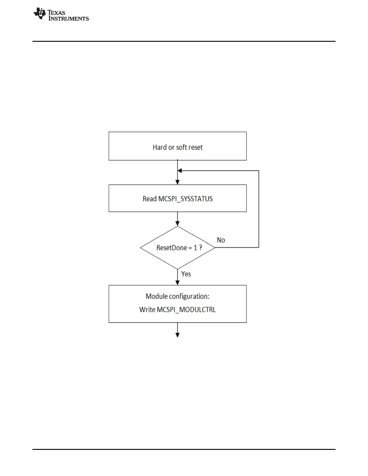
8.5 Module Initialization
Figure 8-14. Flow Chart – Module Initialization
Before the ResetDone bit is set, the clocks CLK and CLKSPIREF must be provided to the module. To
avoid hazardous behavior, reset the module before changing from master mode to slave mode or from
slave mode to master mode.
8.5.1 Common Transfer Sequence
The SPI module allows the transfer of one or several words, according to different modes:
• Master normal, master turbo, slave
• Transmit – receive
• Write and read requests: interrupts, DMA
• SPIEN lines assertion and deassertion: automatic, manual
For all these flows, the host process contains the main process and the interrupt routines. The interrupt
routines are called on the interrupt signals, or by an internal call if the module is used in polling mode.