www.ti.com
Functional Description
121
SWRU543–January 2019
Submit Documentation Feedback
Copyright © 2019, Texas Instruments Incorporated
Direct Memory Access (DMA)
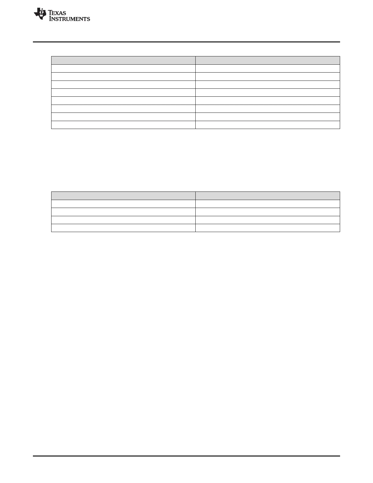
Table 4-2. Channel Control Memory
Offset Channel
0x0 Channel 0 – primary
0x10 Channel 1 – primary
….
0x1F0 Channel 31 – primary
0x200 Channel 0 – alternate
0x210 Channel 1 – alternate
….
0x3F0 Channel 31 – alternate
Table 4-3 shows an individual control structure entry in the control table. Each entry is aligned on a 16-
byte boundary. The entry contains four long words: the source end pointer, the destination end pointer, the
control word, and an unused entry. The end pointers point to the ending address of the transfer and are
inclusive. If the source or destination is nonincrementing (as for a peripheral register), the pointer should
point to the transfer address.
Table 4-3. Individual Control Structure
Offset Description
0x000 Source end pointer
0x004 Destination end pointer
0x008 Control word
0x00C Reserved
Transfer size is part of the control word. At the end of a transfer, the transfer size indicates 0, and the
transfer mode indicates "stopped." Because the control word is modified by the µDMA controller, it must
be reconfigured before each new transfer. The source and destination end pointers are not modified, so
they can be left unchanged if the source or destination addresses remain the same.
Before starting a transfer, a µDMA channel must be enabled by setting the appropriate bit in the DMA
Channel Enable Set (ENASET) register. A channel can be disabled by setting the channel bit in the DMA
Channel Enable Clear (ENACLR) register. At the end of a complete µDMA transfer, the controller
automatically disables the channel.

 Loading...


