www.ti.com
SD-HOST Registers
397
SWRU543–January 2019
Submit Documentation Feedback
Copyright © 2019, Texas Instruments Incorporated
SD Host Controller Interface
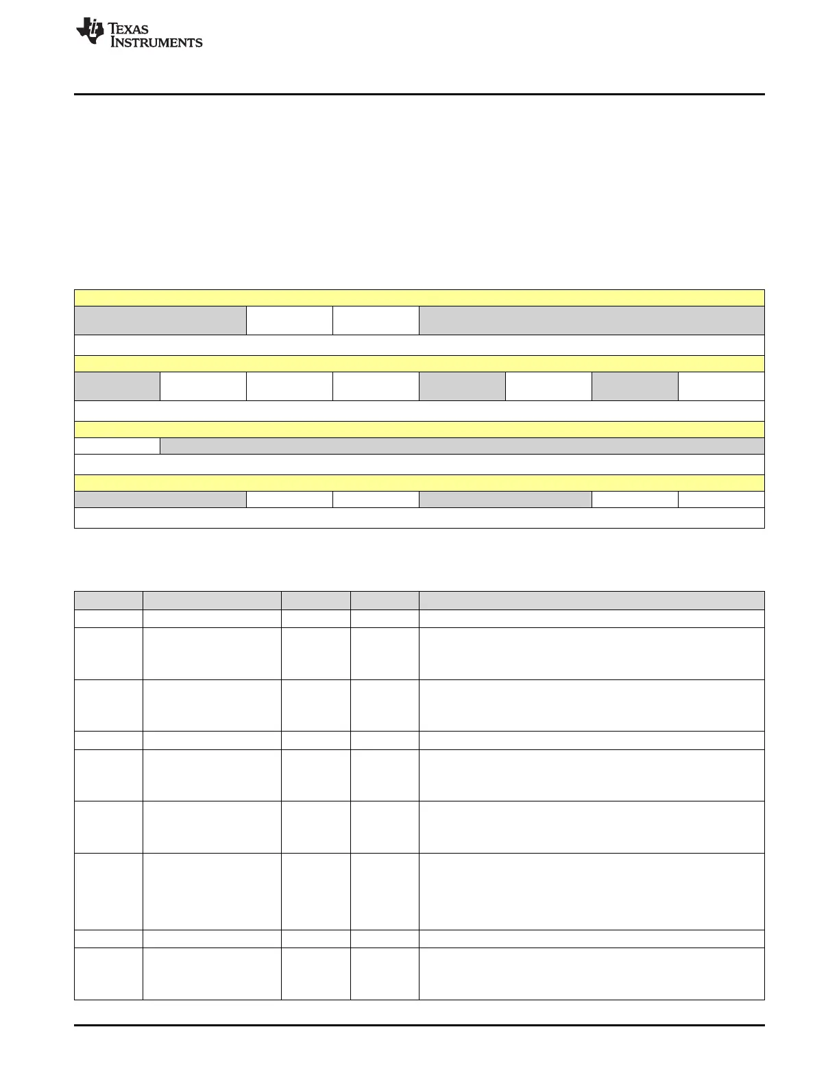
11.7.15 MMCHS_IE Register (Offset = 234h) [reset = 0h]
Interrupt SD Enable register
MMCHS_IE is shown in Figure 11-16 and described in Table 11-19.
Return to Summary Table.
This register allows to enable or disable the module to set status bits, on an event-by-event basis.
MMCHS_IE[31:16] = Error Interrupt Status Enable
MMCHS_IE[15:0] = Normal Interrupt Status Enable
Figure 11-16. MMCHS_IE Register
31 30 29 28 27 26 25 24
RESERVED BADA_ENABL
E
CERR_ENABL
E
RESERVED
R-0h R/W-0h R/W-0h R-0h
23 22 21 20 19 18 17 16
RESERVED DEB_ENABLE DCRC_ENABL
E
DTO_ENABLE RESERVED CEB_ENABLE RESERVED CTO_ENABLE
R-0h R/W-0h R/W-0h R/W-0h R-0h R/W-0h R-0h R/W-0h
15 14 13 12 11 10 9 8
NULL RESERVED
R-0h R-0h
7 6 5 4 3 2 1 0
RESERVED BRR_ENABLE BWR_ENABLE RESERVED TC_ENABLE CC_ENABLE
R-0h R/W-0h R/W-0h R-0h R/W-0h R/W-0h
LEGEND: R/W = Read/Write; R = Read only; W1toCl = Write 1 to clear bit; -n = value after reset
Table 11-19. MMCHS_IE Register Field Descriptions
Bit Field Type Reset Description
31-30 RESERVED R 0h
29 BADA_ENABLE R/W 0h
Bad access to data space interrupt enable
0h = Masked
1h = Enabled
28 CERR_ENABLE R/W 0h
Card error interrupt enable
0h = Masked
1h = Enabled
27-23 RESERVED R 0h
22 DEB_ENABLE R/W 0h
Data end bit error interrupt enable
0h = Masked
1h = Enabled
21 DCRC_ENABLE R/W 0h
Data CRC error interrupt enable
0h = Masked
1h = Enabled
20 DTO_ENABLE R/W 0h
Data time-out error interrupt enable
0h = The data time-out detection is deactivated. The host controller
provides the clock to the card until the card sends the data or the
transfer is aborted.
1h = The data time-out detection is enabled.
19 RESERVED R 0h
18 CEB_ENABLE R/W 0h
Command end bit error interrupt enable
0h = Masked
1h = Enabled