www.ti.com
I2S Registers
415
SWRU543–January 2019
Submit Documentation Feedback
Copyright © 2019, Texas Instruments Incorporated
Inter-Integrated Sound (I2S) Multichannel Audio Serial Port
12.5 I2S Registers
Control registers for the McASP are summarized in Table 12-3. The control registers are accessed
through the peripheral configuration port. The receive buffer registers (RBUF) and transmit buffer registers
(XBUF) can also be accessed through the DMA port, as listed in Table 12-4. See the device-specific data
manual for the memory address of these registers.
Control registers for the McASP Audio FIFO (AFIFO) are summarized in Table 12-5. The AFIFO Write
FIFO (WFIFO) and Read FIFO (RFIFO) have independent control and status registers. The AFIFO control
registers are accessed through the peripheral configuration port. See the device-specific data manual for
the memory address of these registers.
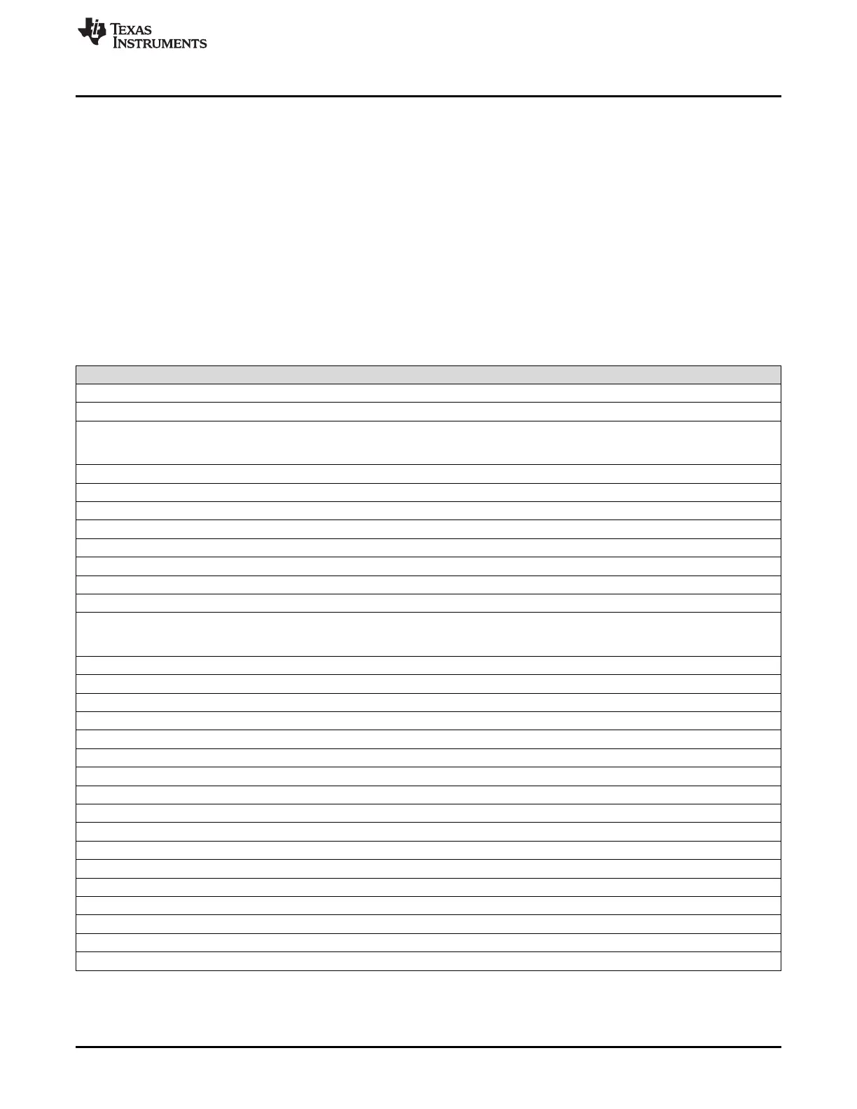
Table 12-3 lists the memory-mapped registers for the I2S. All register offset addresses not listed in
Table 12-3 should be considered as reserved locations and the register contents should not be modified.
Base address is 0x4401C000.
(1)
Writes to XRBUF originate from peripheral configuration port only when XBUSEL = 1 in XFMT.
(2)
Reads from XRBUF originate on peripheral configuration port only when RBUSEL = 1 in RFMT.
Table 12-3. I2S Registers Accessed Through Peripheral Configuration Port
Offset Acronym Register Name Section
14h PDIR Pin Direction Section 12.5.3
44h GBLCTL Global Control Section 12.5.6
60h RGBLCTL Receiver Global Control. Alias of GBLCTL, only receive
bits are affected - allows receiver to be reset
independently from transmitter
Section 12.5.7
64h RMASK Receive Format Unit Bit Mask Section 12.5.8
68h RFMT Receive Bit Stream Format Section 12.5.9
6Ch AFSRCTL Receive Frame Sync Control Section 12.5.10
78h RTDM Receive TDM Time Slot 0-31 Section 12.5.11
7Ch RINTCTL Receiver Interrupt Control Section 12.5.12
80h RSTAT Receiver Status Section 12.5.13
84h RSLOT Current Receive TDM Time Slot Section 12.5.14
8Ch REVTCTL Receiver DMA Event Control Section 12.5.15
A0h XGBLCTL Transmitter Global Control. Alias of GBLCTL, only
transmit bits are affected - allows transmitter to be reset
independently from receiver
Section 12.5.16
A4h XMASK Transmit Format Unit Bit Mask Section 12.5.17
A8h XFMT Transmit Bit Stream Format Section 12.5.18
ACh AFSXCTL Transmit Frame Sync Control Section 12.5.19
B0h ACLKXCTL Transmit Clock Control Section 12.5.20
B4h AHCLKXCTL Transmit High-frequency Clock Control Section 12.5.21
B8h XTDM Transmit TDM Time Slot 0-31 Section 12.5.22
BCh XINTCTL Transmitter Interrupt Control Section 12.5.23
C0h XSTAT Transmitter Status Section 12.5.24
C4h XSLOT Current Transmit TDM Time Slot Section 12.5.25
C8h XCLKCHK Transmit Clock Check Control
CCh XEVTCTL Transmitter DMA Event Control Section 12.5.26
180h SRCTL0 Serializer Control Register 0 Section 12.5.27
184h SRCTL1 Serializer Control Register 1 Section 12.5.27
200h XBUF0
(1)
Transmit Buffer Register for Serializer 0 Section 12.5.28
204h XBUF1
(1)
Transmit Buffer Register for Serializer 1 Section 12.5.28
280h RBUF0
(2)
Receive Buffer Register for Serializer 0 Section 12.5.29
284h RBUF1
(2)
Receive Buffer Register for Serializer 1 Section 12.5.29