www.ti.com
CRC Registers
757
SWRU543–January 2019
Submit Documentation Feedback
Copyright © 2019, Texas Instruments Incorporated
Cyclical Redundancy Check (CRC)
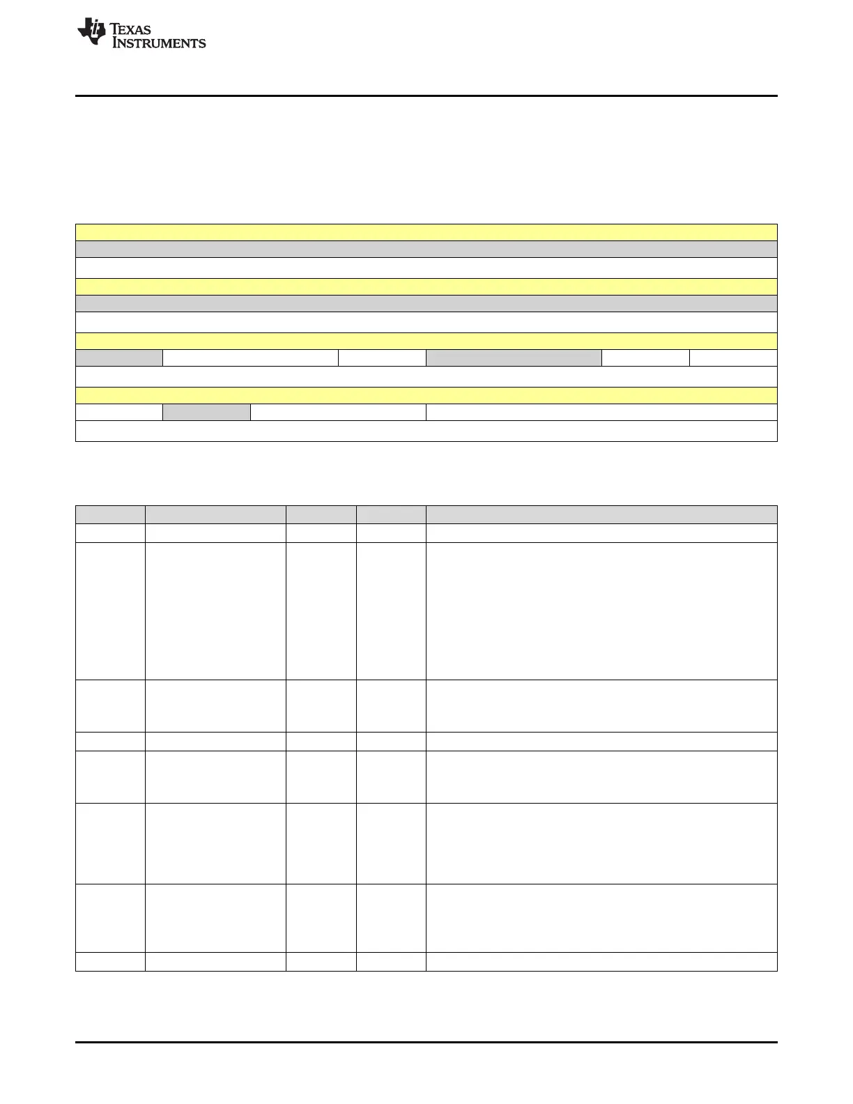
20.3.1 CRCCTRL Register (Offset = C00h) [reset = 0h]
CRCCTRL is shown in Figure 20-1 and described in Table 20-4.
Return to Summary Table.
The CRC Control (CRCCTRL) register configures control of the CRC.
Figure 20-1. CRCCTRL Register
31 30 29 28 27 26 25 24
RESERVED
R-0h
23 22 21 20 19 18 17 16
RESERVED
R-0h
15 14 13 12 11 10 9 8
RESERVED INIT SIZE RESERVED RESINV OBR
R-0h R/W-0h R/W-0h R-0h R/W-0h R/W-0h
7 6 5 4 3 2 1 0
BR RESERVED ENDIAN TYPE
R/W-0h R-0h R/W-0h R/W-0h
LEGEND: R/W = Read/Write; R = Read only; W1toCl = Write 1 to clear bit; -n = value after reset
Table 20-4. CRCCTRL Register Field Descriptions
Bit Field Type Reset Description
31-15 RESERVED R 0h
14-13 INIT R/W 0h
CRC Initialization
Determines initialization value of CRC. This field is self-clearing.
With the first write to the CRC Data Input (CRCDIN) register, this
value clears to zero and remains zero for the rest of the operation
unless written again.
0h = Use the CRCSEED register context as the starting value
1h = Reserved
2h = Initialize to all 0s
3h = Initialize to all 1s
12 SIZE R/W 0h
Input Data Size
0h = 32-bit (word)
1h = 8-bit (byte)
11-10 RESERVED R 0h
9 RESINV R/W 0h
Result Inverse Enable
0h = No effect
1h = Invert the result bits before storing in the CRCRSLTPP register.
8 OBR R/W 0h
Output Reverse Enable
Refer to Table 20-2 for more information regarding bit reversal.
0h = No change to result.
1h = Bit reverse the output result byte before storing to CRCRSLTPP
register. The reversal is applied to all bytes in a word.
7 BR R/W 0h
Bit Reverse Enable
See Table 20-2 for more information regarding bit reversal.
0h = No change to result.
1h = Bit reverse the input byte for all bytes in a word.
6 RESERVED R 0h