GPIO Registers
www.ti.com
162
SWRU543–January 2019
Submit Documentation Feedback
Copyright © 2019, Texas Instruments Incorporated
General-Purpose Input/Outputs (GPIOs)
5.5.1 GPIODATA Register (offset = 0h) [reset = 0h]
GPIODATA is shown in Figure 5-4 and described in Table 5-4.
The GPIODATA register is the data register. In software control mode, values written in the GPIODATA
register are transferred onto the GPIO port pins if the respective pins have been configured as outputs
through the GPIO Direction (GPIODIR) register.
The GPIODATA register has 256 aliased addresses from offset 0x000 to 0x3FF. A different address alias
is used to directly read or write any combination of the 8 signal bits. This feature can help avoid time-
consuming read-modify-writes and bit-masking operation for read-in software.
In this scheme, to write to GPIODATA, the corresponding bits in the mask, represented by the address
bus bits [9:2], must be set. Otherwise, the bit values remain unchanged by the write.
Similarly, the values read from this register are determined for each bit by the mask bit derived from the
alias address used to access the data register, bits [9:2]. Bits set in the address mask cause the
corresponding bits in GPIODATA to be read, and bits that are clear in the address mask cause the
corresponding bits in GPIODATA to be read as 0, regardless of their value.
A read from GPIODATA returns the last bit value written if the respective pins are configured as outputs,
or it returns the value on the corresponding input pin when these are configured as inputs. All bits are
cleared by a reset.
Figure 5-4. GPIODATA Register
31 30 29 28 27 26 25 24 23 22 21 20 19 18 17 16 15 14 13 12 11 10 9 8 7 6 5 4 3 2 1 0
RESERVED DATA
R-0h R/W-0h
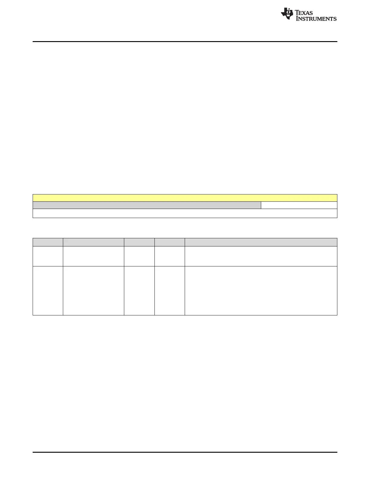
Table 5-4. GPIODATA Register Field Descriptions
Bit Field Type Reset Description
31-8 RESERVED R 0h
Software should not rely on the value of a reserved bit. To provide
compatibility with future products, the value of a reserved bit should
be preserved across a read-modify-write operation.
7-0 DATA R/W 0h
GPIO Data
This register is virtually mapped to 256 locations in the address
space. To facilitate the reading and writing of data to these registers
by independent drivers, the data read from and written to the
registers are masked by the eight address lines [9:2]. Reads from
this register return its current state. Writes to this register only affect
bits that are not masked by ADDR[9:2] and are configured as
outputs.