Power Management Control Architecture
www.ti.com
520
SWRU543–January 2019
Submit Documentation Feedback
Copyright © 2019, Texas Instruments Incorporated
Power, Reset, and Clock Management
As a result, the power mode of the chip can be different from the sleep state of the application software
code. For example, when the application code requests for LPDS mode it is granted immediately;
however, if the network processor or WLAN is active at that time, the chip does not enter LPDS mode until
they are finished. In that case, the application processor is held under reset, which produces a safe result
for the software, regardless of when the digital logic gets power-gated and when the voltage drops to 0.9
V. Similarly, on wake event for a particular subsystem, the chip as a whole transitions into active state
(VDD_DIG = 1.2 V, 40-MHz XOSC and PLL-enabled) and then only that subsystem is awakened from
LPDS. The other subsystems are held in reset until their respective wake events.
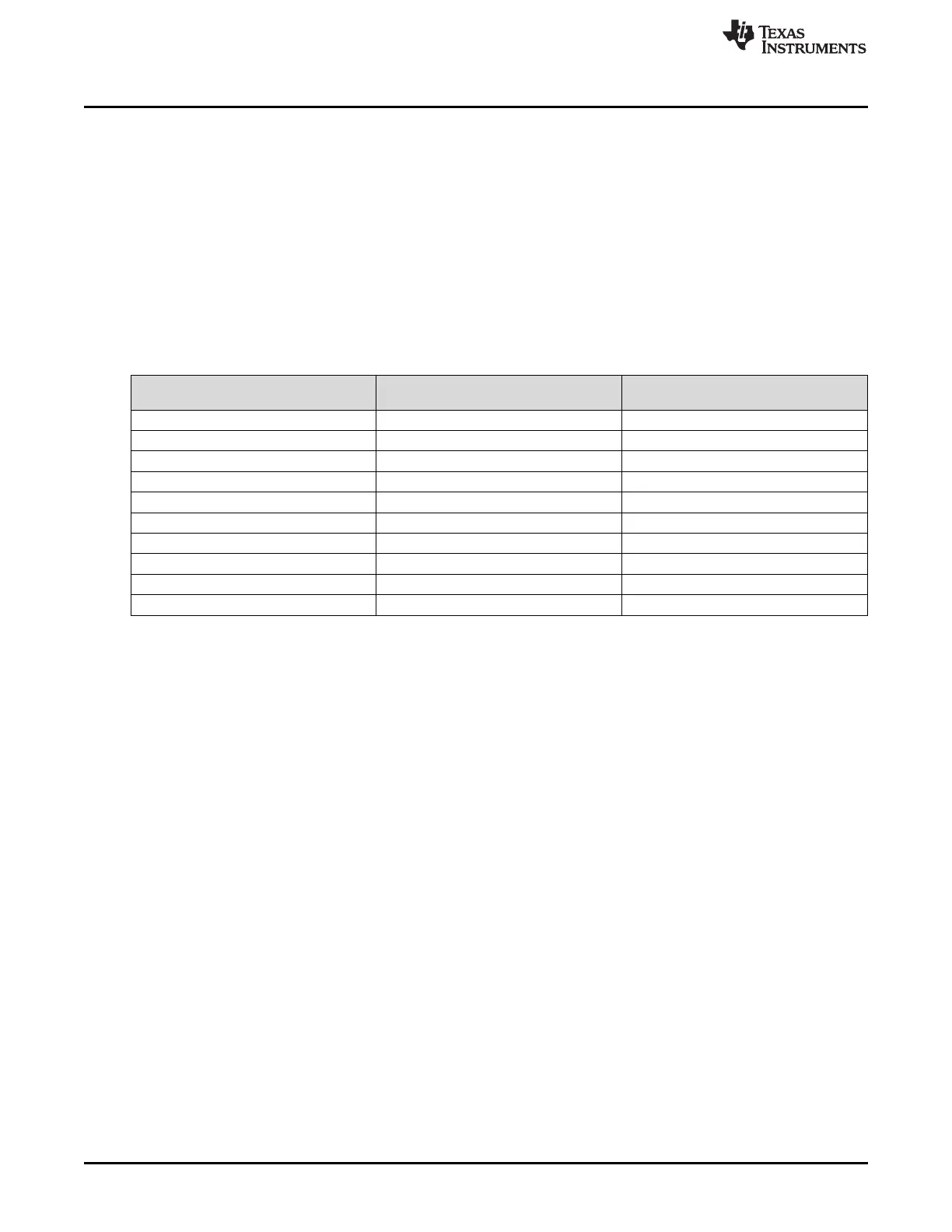
Table 15-1 shows the feasible combinations of power states between the application processor and the
network (including WLAN) subsystems). See the CC3235S and CC3235SF SimpleLink™ Wi-Fi
®
, Dual-
Band, Single-Chip Solution data sheet for details of current consumption for these combinations.
Table 15-1. Possible PM State Combinations of Application Processor and Network Subsystem
(NWP+WLAN)
Application Processor (MCU) Software
State
Network Processor and WLAN
Software State
Resulting Power State of Chip, Core
Logic Voltage, and Clock
ACTIVE ACTIVE ACTIVE (1.2 V, 80 MHz, 32 kHz)
ACTIVE SLEEP ACTIVE (1.2 V, 80 MHz, 32 kHz)
ACTIVE LPDS (Fake-LPDS) ACTIVE (1.2 V, 80 MHz, 32 kHz)
SLEEP ACTIVE ACTIVE (1.2 V, 80 MHz, 32 kHz)
SLEEP SLEEP ACTIVE (1.2 V, 80 MHz, 32 kHz)
SLEEP LPDS (Fake-LPDS) ACTIVE (1.2 V, 80 MHz, 32 kHz)
LPDS (Fake-LPDS) ACTIVE ACTIVE (1.2 V, 80 MHz, 32 kHz)
LPDS (Fake-LPDS) SLEEP ACTIVE (1.2 V, 80 MHz, 32 kHz)
LPDS (Fake-LPDS) LPDS (Fake-LPDS) LPDS (True-LPDS) (0.9 V, 32 kHz)
Request For HIBERNATE Don't Care HIBERNATE (0 V, 32 kHz)
Figure 15-3 shows the high-level architecture of the CC32xx SoC-level power management.
15.2.1 Global Power-Reset-Clock Manager (GPRCM)
The global power-reset-clock manager (GPRCM) module receives the sleep requests from the
subsystems and the wake events from associated sources. Based on sleep requests and wake events,
the GPRCM controls the clock sources, PLL, power switches, and the PMU to change or gate/ungate the
supply, clocks, and resets to the following subsystems:
• Application processor (APPS)
• Networking processor (NWP)
• WLAN MAC and PHY processors (WLAN)
Programmable system clock frequency (using PLL) is not supported in the CC32xx, due to coexistence
reasons. For ease of programming and system robustness, application code has limited access to the chip
power and clock management infrastructure in CC32xx. The software interface to power management is
limited to a subset of GPRCM registers, which are accessed through a set of easy-to-use API functions
described in Section 15.3.