CC3235
IO
PIN MUX
RF TEST
PM TEST
ANA2-DCDC
External Supply
Sensing Ckt
Switch Driver
32-kHz Crystal Oscillator
source select mux
Crystal
Oscillator
Ext Pullup
Sensing Ckt
S7
S8
S9
S10
ADC_CH3
ADC_CH2
ADC_CH1
ADC_CH0
ADC
29 30 50 53 57 58 59 60
525144 45 47 46
EN
VIN_DCDC_DIG
DCDC_ANA2_SW_P
VDD_ANA2
DCDC_ANA2_SW_N
GND
NC
100-k
pullup
RTC_XTAL_P
RTC_XTAL_N
S5 S6 S2 S3
S4
S1
analog signal switch
EN
Digital Only
Pads
Supply
Input
(VBAT)
Available For
Digital Signal
(in/out)
External 32.768 kHz
Square Wave Source
Available For
Digital Signal
(out only)
Digital
Peripherals
ANTSEL1
ANTSEL2
Pins Shared By Analog and Digital*
*
*
Pins Shared By Analog and Digital*
power FET
Special Analog/Digital Pins
www.ti.com
586
SWRU543–January 2019
Submit Documentation Feedback
Copyright © 2019, Texas Instruments Incorporated
I/O Pads and Pin Multiplexing
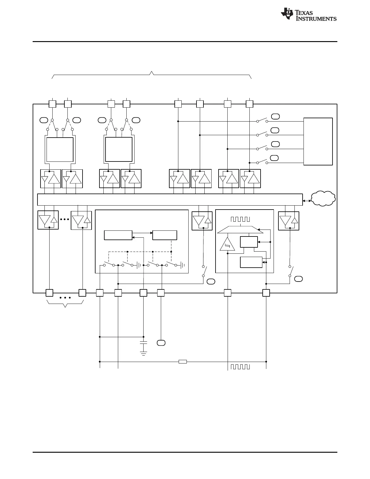
Figure 16-2. Board Configuration to Use Pins 45 and 52 as Digital Signals
(1) Board level configuration required to use pins 45 and 52 for digital signals.