Overview
www.ti.com
458
SWRU543–January 2019
Submit Documentation Feedback
Copyright © 2019, Texas Instruments Incorporated
Analog-to-Digital Converter (ADC)
13.1 Overview
The CC32xx device provides a general-purpose, multichannel Analog-to-Digital Converter (ADC). Each
ADC channel supports 12-bit conversion resolution with sampling periodicity of 16 µS (62.5 Ksps/channel).
Each channel has an associated FIFO and DMA. For detailed electrical characteristics of the ADC, see
CC3135 SimpleLink™ Wi-Fi® and Internet-of-Things Solution for MCU Applications.
13.2 Key Features
• Total of eight channels
– Four external analog input channels for user applications
– Four internal channels reserved for SimpleLink™ subsystem (network and Wi-Fi
®
).
• 12-bit resolution
• Fixed sampling rate of 16 µs per channel. Equivalent to 62.5K samples/sec per channel
• Fixed round-robin sampling across all channels
• Samples are uniformly spaced and interleaved. Multiple user channels can be combined to realize
higher sampling rate. For example, all four channels can be shorted together to get an aggregate
sampling rate of 250K samples/sec.
• DMA interface to transfer data to the application RAM; dedicated DMA channel for each channel
• Capability to time-stamp ADC samples using 17-bit timer running on a 40-MHz clock. The user can
read the timestamp and the sample from the FIFO registers. Each sample in the FIFO contains actual
data and a timestamp.
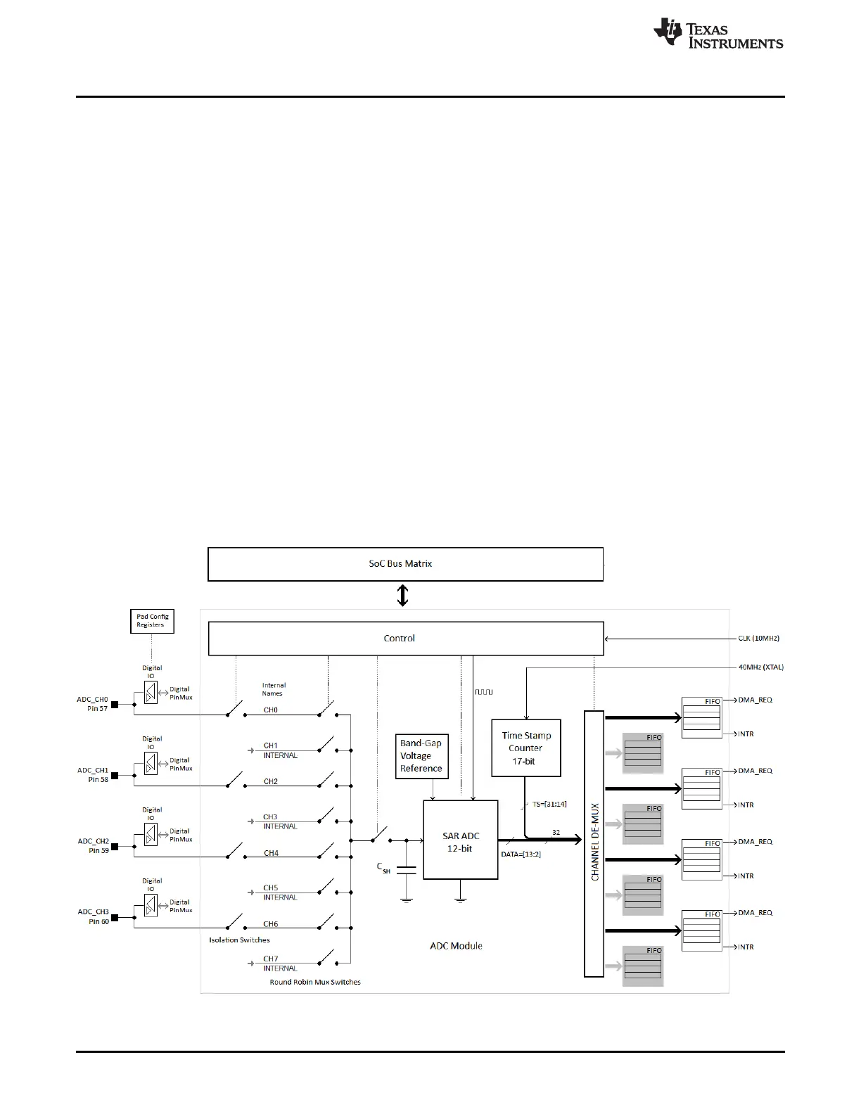
Figure 13-1 shows the architecture of the ADC module in the CC32xx.
Figure 13-1. Architecture of the ADC Module in CC32xx