www.ti.com
Functional Description
65
SWRU543–January 2019
Submit Documentation Feedback
Copyright © 2019, Texas Instruments Incorporated
Cortex
®
-M4 Processor
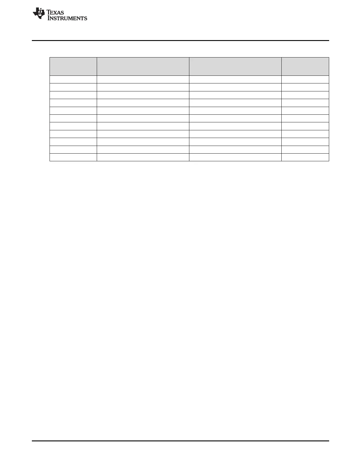
Table 2-7. CC32xx Application Processor Interrupts (continued)
Interrupt Number
(Bit in Interrupt
Registers)
Vector Address or Offset Description Type
35 0x0000.00CC 16- or 32-Bit Timer A3A
36 0x0000.00D0 16- or 32-Bit Timer A3B
46 0x0000.00F8 uDMA Software Intr
47 0x0000.00FC uDMA Error Intr
161 0x0000.02C4 I2S
163 0x0000.02CC Camera
168 0x0000.02E0 RAM WR Error
171 0x0000.02EC Network Intr
175 0x0000.02FC Shared SPI interrupt (for SFLASH)
176 0x0000.0300 SPI
177 0x0000.0304 Link SPI (APPS to NWP)
2.2.4.3 Exception Handlers
The processor handles exceptions using:
• Interrupt service routines (ISRs): Interrupts (IRQx) are the exceptions handled by ISRs.
• Fault handlers: Hard fault, memory-management fault, usage fault, and bus fault are fault exceptions
handled by the fault handlers.
• System handlers: NMI, PendSV, SVCall, SysTick, and the fault exceptions are all system exceptions
handled by system handlers.
2.2.4.4 Vector Table
The vector table contains the reset value of the stack pointer and the start addresses, also called
exception vectors, for all exception handlers. The vector table is constructed using the vector address or
offset shown in Table 2-6. Figure 2-5 shows the order of the exception vectors in the vector table. The
least significant bit of each vector must be 1, indicating that the exception handler is thumb code.
On system reset, the vector table is fixed at address 0x0000 0000. Privileged software can write to the
Vector Table Offset (VTABLE) register to relocate the vector table start address to a different memory
location, in the range 0x0000 0400 to 0x3FFF FC00. When configuring the VTABLE register, the offset
must be aligned on a 1024-byte boundary.