R01UH0823EJ0100 Rev.1.00 Page 1756 of 1823
Jul 31, 2019
RX23W Group 51. Electrical Characteristics
Note 1. The value of the D/A converter is the value of the power supply current including the reference current.
Note 2. Current consumed only by the USB module.
Note 3. Includes the current supplied from the pull-up resistor of the USB0_DP pin to the pull-down resistor of the host device, in
addition to the current consumed by this MCU during the suspended state.
Note 4. Current consumed by the power supplies (VCC and VCC_USB).
Note 5. Current consumed only by the comparator B module.
Note 6. Current consumed by the power supply (VCC).
Note 7. When VCC = AVCC0 = VCC_USB = 3.3 V.
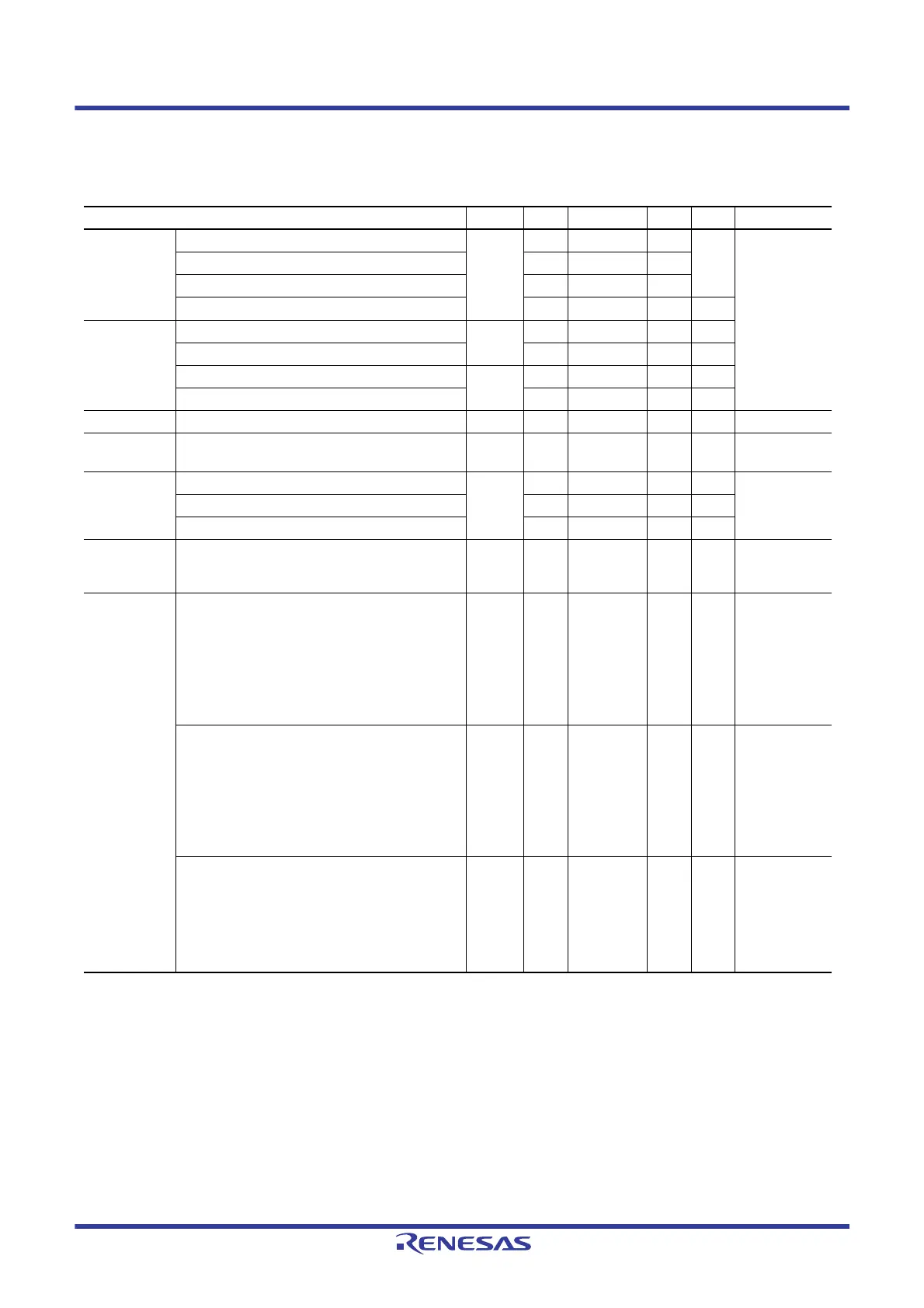
Table 51.11 DC Characteristics (9)
Conditions: 1.8 V ≤ VCC = VCC_USB = AVCC0 = VCC_RF = AVCC_RF ≤ 3.6 V, VSS = AVSS0 = VSS_USB = VSS_RF = 0 V,
T
a
= –40 to +85°C
Item Symbol Min. Typ.*
7
Max. Unit Test Conditions
Analog power
supply current
During A/D conversion (at high-speed conversion) I
AVCC
—0.71.7mA
During A/D conversion (in low-current mode) — 0.6 1.0
During D/A conversion (per channel)*
1
—0.40.8
Waiting for A/D and D/A conversion (all units) — — 0.4 μA
Reference
power supply
current
During A/D conversion (at high-speed conversion) I
REFH0
— 25 150 μA
Waiting for A/D conversion (all units) — — 60 nA
During D/A conversion (per channel) I
REFH
— 50 100 μA
Waiting for D/A conversion (all units) — — 100 nA
LVD1 — I
LVD
—0.15—μA
Temperature
sensor*
6
—I
TEMP
—75—μA
Comparator B
operating
current*
6
Window mode I
CMP
*
5
— 12.5 28.6 μA
Comparator high-speed mode (per channel) — 3.2 16.2 μA
Comparator low-speed mode (per channel) — 1.7 4.4 μA
CTSU
operating
current
When sleep mode
Base clock frequency: 2MHz
Pin capacitance: 50pF
I
CTSU
— 150 — μA
USB operating
current*
4
During USB communication operation under the
following settings and conditions
Host controller operation is set to full-speed
mode
Bulk OUT transfer (64 bytes) × 1,
bulk IN transfer (64 bytes) × 1
Connect peripheral devices via a 1-meter USB
cable from the USB port.
I
USBH
*
2
—4.3
(VCC)
0.9
(VCC_USB)
—mA
During USB communication operation under the
following settings and conditions
Function controller operation is set to full-speed
mode
Bulk OUT transfer (64 bytes) × 1,
bulk IN transfer (64 bytes) × 1
Connect the host device via a 1-meter USB
cable from the USB port.
I
USBF
*
2
—3.6
(VCC)
1.1
(VCC_USB)
—mA
During suspended state under the following setting
and conditions
Function controller operation is set to full-speed
mode (pull up the USB0_DP pin)
Software standby mode
Connect the host device via a 1-meter USB
cable from the USB port.
I
SUSP
*
3
—0.35
(VCC)
170
(VCC_USB)
—μA

 Loading...


