R01UH0823EJ0100 Rev.1.00 Page 916 of 1823
Jul 31, 2019
RX23W Group 32. USB 2.0 Host/Function Module (USBc)
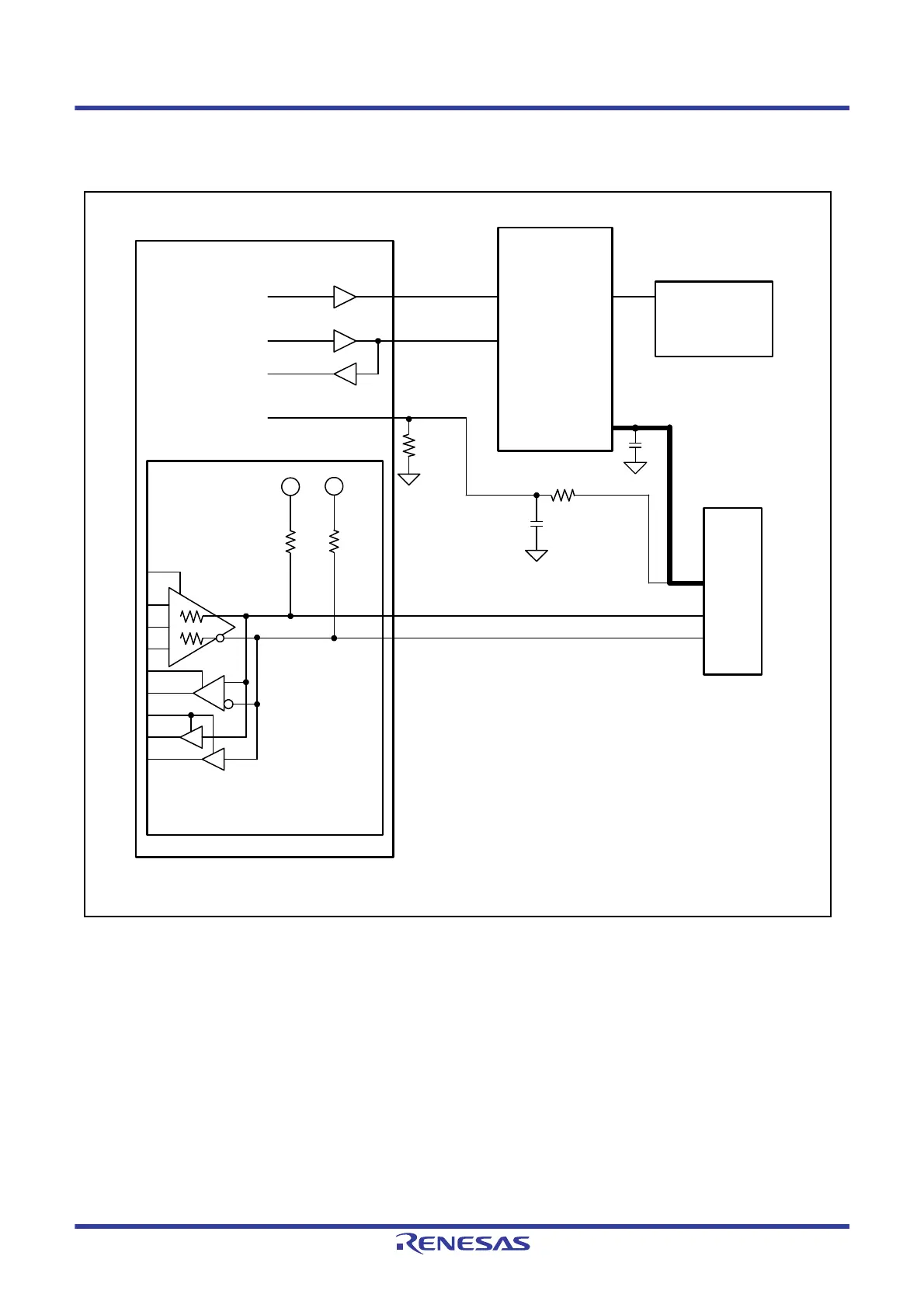
Figure 32.4 shows an example of functional connection of the USB connector with Battery Charging Specification
Revision 1.2 supported.
Figure 32.4 Functional Connection Sample of USB Connector with Battery Charging Specification Rev.1.2
Supported
External connection
MCU
SCL0
SDA0
SCL0
SDA0
VBUS
USB0_DP
USB
B connector
D+
D–
VBUS
USB
transceiver
Charging IC
supporting BC 1.2
USB0_DM
R
PU
Charging battery
*1, *3
Z
DRV
Z
DRV
Z
DRV
: Output impedance
R
PU
: Pull-up resistor
R
PU
USB0_VBUS
100
0.1 µF
10 k
*2
P16 or PB5
Note 1. When Battery Charging Spec. Rev.1.2 is to be
supported, ensure that the VBUS wiring width is enough
for at least 1.5 A (shown in bold lines).
Note 2. Use a resistor value such that the discharging time of
VBUS is within 500 ms.
Note 3. Design the board so that the total VBUS capacitance
ranges from 1.0 to 10 µF.

 Loading...


