I2C Registers
www.ti.com
236
SWRU543–January 2019
Submit Documentation Feedback
Copyright © 2019, Texas Instruments Incorporated
Inter-Integrated Circuit (I
2
C) Interface
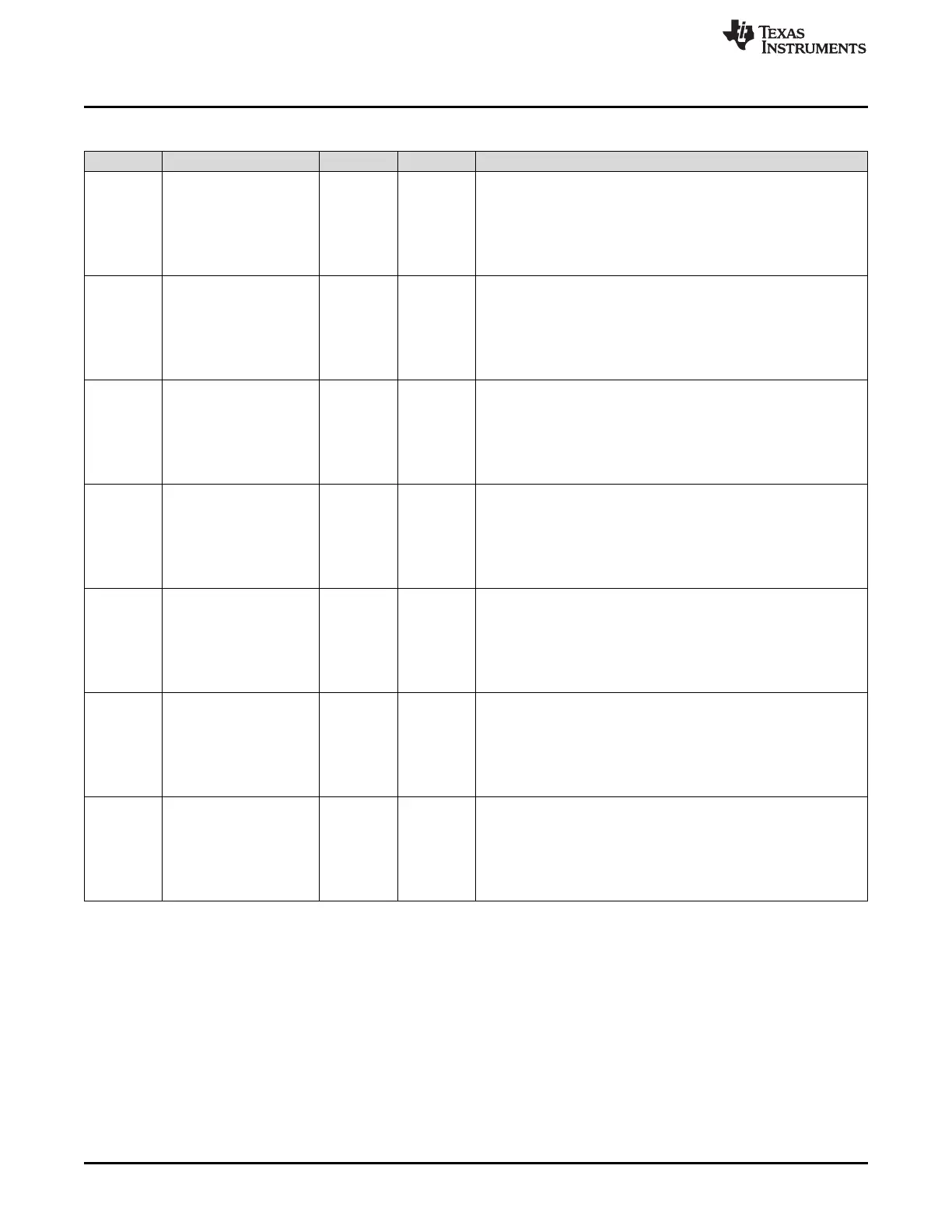
Table 7-11. I2CMMIS Register Field Descriptions (continued)
Bit Field Type Reset Description
6 STOPMIS R 0h
STOP Detection Interrupt Mask
This bit is cleared by writing a 1 to the STOPIC bit in the I2CMICR
register.
0h = No interrupt.
1h = An unmasked STOP Detection interrupt was signaled and is
pending.
5 STARTMIS R 0h
START Detection Interrupt Mask
This bit is cleared by writing a 1 to the STARTIC bit in the I2CMICR
register.
0h = No interrupt.
1h = An unmasked START Detection interrupt was signaled and is
pending.
4 NACKMIS R 0h
Address/Data NACK Interrupt Mask
This bit is cleared by writing a 1 to the NACKIC bit in the I2CMICR
register.
0h = No interrupt.
1h = An unmasked Address/Data NACK interrupt was signaled and
is pending.
3 DMATXMIS R 0h
Transmit DMA Interrupt Status
This bit is cleared by writing a 1 to the DMATXIC bit in the I2CMICR
register.
0h = No interrupt.
1h = An unmasked transmit DMA complete interrupt was signaled
and is pending.
2 DMARXMIS R 0h
Receive DMA Interrupt Status
This bit is cleared by writing a 1 to the DMARXIC bit in the I2CMICR
register.
0h = No interrupt.
1h = An unmasked receive DMA complete interrupt was signaled
and is pending.
1 CLKMIS R 0h
Clock Timeout Masked Interrupt Status
This bit is cleared by writing a 1 to the CLKIC bit in the I2CMICR
register.
0h = No interrupt.
1h = An unmasked clock timeout interrupt was signaled and is
pending.
0 MIS R 0h
Clock Timeout Masked Interrupt Status
This bit is cleared by writing a 1 to the CLKIC bit in the I2CMICR
register.
0h = No interrupt.
1h = An unmasked clock timeout interrupt was signaled and is
pending.