Functional Description
www.ti.com
314
SWRU543–January 2019
Submit Documentation Feedback
Copyright © 2019, Texas Instruments Incorporated
General-Purpose Timers
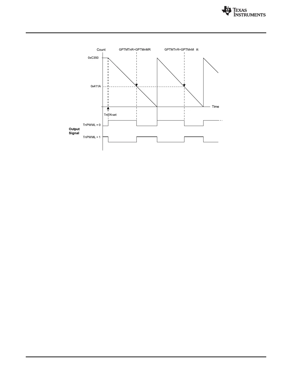
Figure 9-4. 16-Bit PWM Mode Example
9.3.3 DMA Operation
Each timer has a dedicated µDMA channel and can provide a request signal to the µDMA controller. Pulse
requests are generated by a timer using its own dma_req signal. A dma_done signal is provided from the
µDMA to each timer, to indicate transfer completion and trigger a µDMA done interrupt (DMAnRIS) in the
GPTM Raw Interrupt Status Register (GPTMRIS) register. The request is a burst type, and occurs
whenever a timer raw interrupt condition occurs. The arbitration size of the µDMA transfer should be set to
the amount of data that should be transferred whenever a timer event occurs.
For example, to transfer 256 items, or 8 items at a time every 10 ms, configure a timer to generate a
periodic time-out at 10 ms. Configure the µDMA transfer for a total of 256 items, with a burst size of 8
items. Each time the timer times out, the µDMA controller transfers 8 items, until all 256 items have been
transferred.
The GPTM DMA Event (GPTMDMAEV) register enables the types of events that can cause a dma_req
signal assertion by the timer module. Application software can enable a dma_req trigger for a match,
capture, or time-out event for each timer using the GPTMDMAEV register. For an individual timer, all
active timer trigger events that have been enabled through the GPTMDMAEV register are ORed together
to create a single dma_req pulse that is sent to the µDMA. When the µDMA transfer has completed, a
dma_done signal is sent to the timer, resulting in a DMAnRIS bit set in the GPTMRIS register.
9.3.4 Accessing Concatenated 16/32-Bit GPTM Register Values
The GPTM is placed into concatenated mode by writing a 0x0 to the GPTMCFG bit field in the GPTM
Configuration (GPTMCFG) register. In this configuration, certain 16/32-bit GPTM registers are
concatenated to form pseudo-32-bit registers. These registers include:
• GPTM Timer A Interval Load (GPTMTAILR) register [15:0]
• GPTM Timer B Interval Load (GPTMTBILR) register [15:0]
• GPTM Timer A (GPTMTAR) register [15:0]
• GPTM Timer B (GPTMTBR) register [15:0]
• GPTM Timer A Value (GPTMTAV) register [15:0]
• GPTM Timer B Value (GPTMTBV) register [15:0]
• GPTM Timer A Match (GPTMTAMATCHR) register [15:0]
• GPTM Timer B Match (GPTMTBMATCHR) register [15:0]