I2S Registers
www.ti.com
424
SWRU543–January 2019
Submit Documentation Feedback
Copyright © 2019, Texas Instruments Incorporated
Inter-Integrated Sound (I2S) Multichannel Audio Serial Port
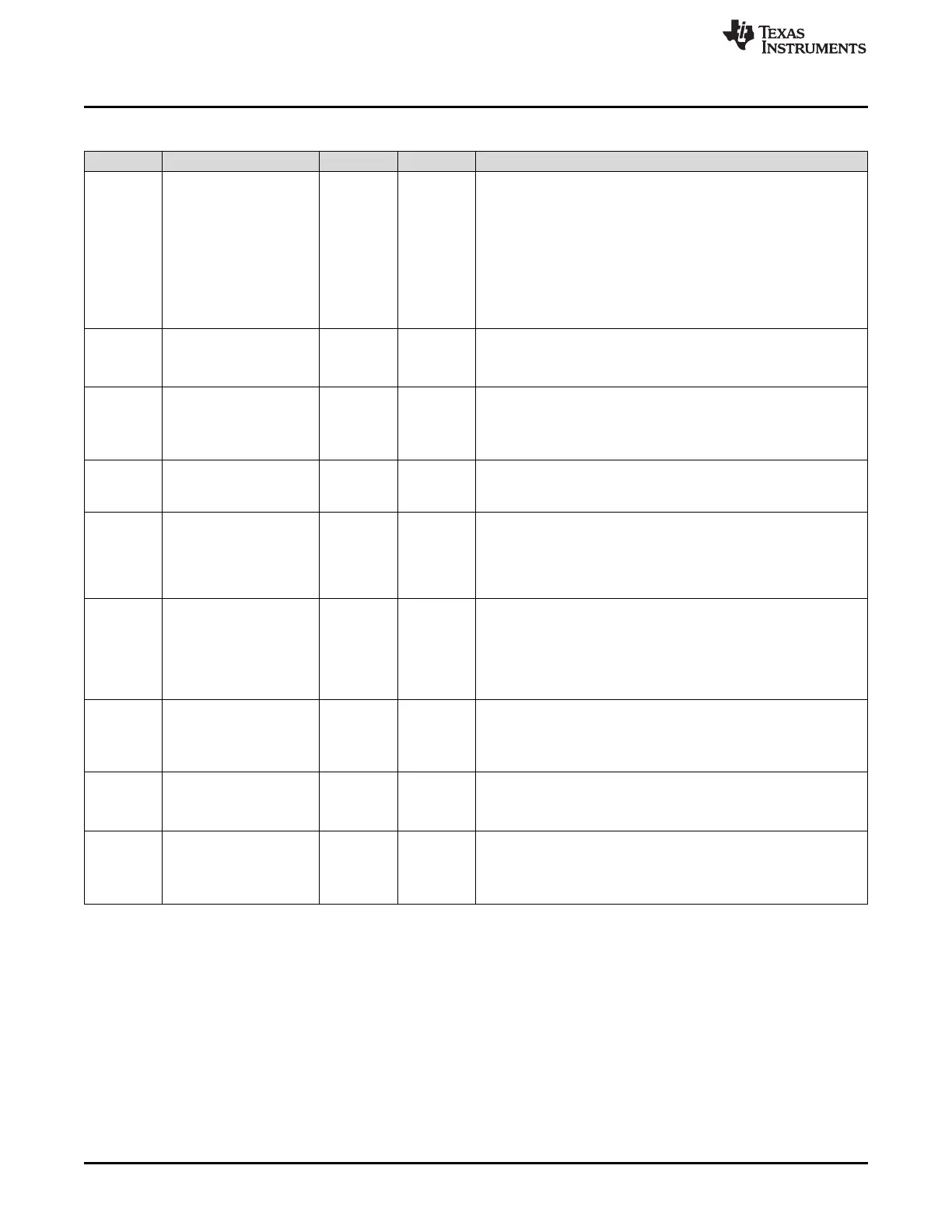
Table 12-11. GBLCTL Register Field Descriptions (continued)
Bit Field Type Reset Description
10 XSRCLR R/W 0h
Transmit serializer clear enable bit. By clearing then setting this bit,
the transmit buffer is flushed to an empty state (XDATA = 1). If
XSMRST = 1, XSRCLR = 1, XDATA = 1, and XBUF is not loaded
with new data before the start of the next active time slot, an
underrun will occur.
0h = Transmit serializers are cleared.
1h = Transmit serializers are active. When the transmit serializers
are first taken out of reset (XSRCLR changes from 0 to 1), the
transmit data ready bit (XDATA) in XSTAT is set to indicate XBUF is
ready to be written.
9 XHCLKRST R/W 0h
Transmit high-frequency clock divider reset enable bit.
0h = Transmit high-frequency clock divider is held in reset.
1h = Transmit high-frequency clock divider is running.
8 XCLKRST R/W 0h
Transmit clock divider reset enable bit.
0h = Transmit clock divider is held in reset. When the clock divider is
in reset, it passes through a divide-by-1 of its input.
1h = Transmit clock divider is running.
7-5 RESERVED R 0h
Reserved. The reserved bit location always returns the default value.
A value written to this field has no effect. If writing to this field,
always write the default value for future device compatibility.
4 RFRST R/W 0h
Receive frame sync generator reset enable bit.
0h = Receive frame sync generator is reset.
1h = Receive frame sync generator is active. When released from
reset, the receive frame sync generator begins counting serial clocks
and generating frame sync as programmed.
3 RSMRST R/W 0h
Receive state machine reset enable bit.
0h = Receive state machine is held in reset.
1h = Receive state machine is released from reset. When released
from reset, the receive state machine immediately begins detecting
frame sync and is ready to receive. Receive TDM time slot begins at
slot 0 after reset is released.
2 RSRCLR R/W 0h
Receive serializer clear enable bit. By clearing then setting this bit,
the receive buffer is flushed.
0h = Receive serializers are cleared.
1h = Receive serializers are active.
1 RHCLKRST R/W 0h
Receive high-frequency clock divider reset enable bit.
0h = Receive high-frequency clock divider is held in reset.
1h = Receive high-frequency clock divider is running.
0 RCLKRST R/W 0h
Receive high-frequency clock divider reset enable bit.
0h = Receive clock divider is held in reset. When the clock divider is
in reset, it passes through a divide-by-1 of its input.
1h = Receive clock divider is running.