Functional Description
www.ti.com
266
SWRU543–January 2019
Submit Documentation Feedback
Copyright © 2019, Texas Instruments Incorporated
SPI (Serial Peripheral Interface)
• Support of both master and slave modes
• Independent DMA requests for read and write
• No dead cycle between two successive words in slave mode
• Multiple SPI word access with a channel using an enabled FIFO
The SPI allows a duplex serial communication between a local host and SPI-compliant external devices
(slaves and masters).
8.2 Functional Description
8.2.1 SPI
Table 8-1 lists the name and description of the SPI used for connection to external SPI-compliant devices.
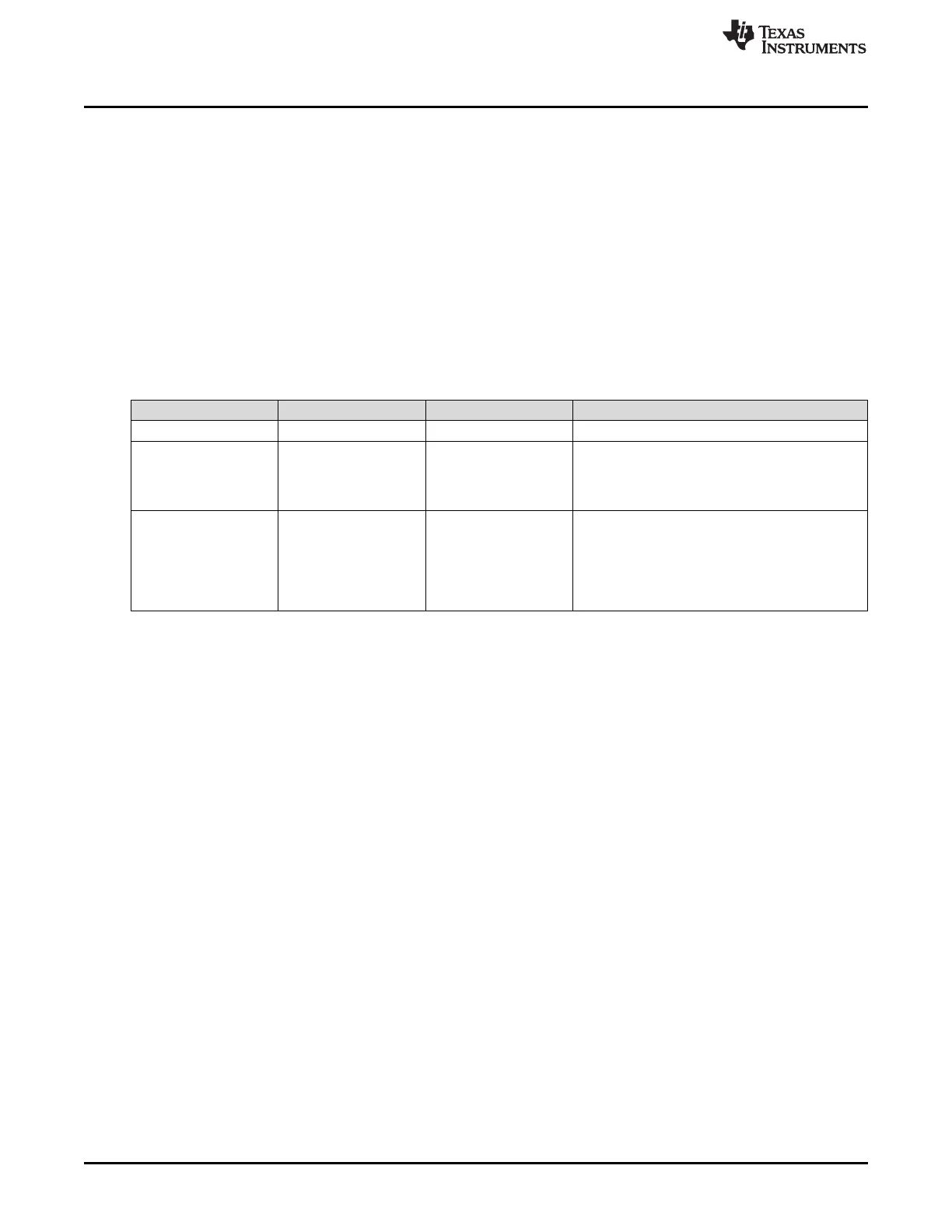
Table 8-1. SPI
Name Type Reset Value Description
MISO/MOSI [1:0] In-Out Z Serial data lines for transmitting and receiving data.
SPICLK In-Out Z
Transmits the serial clock when configured as a
master.
Receives the serial clock when configured as a
slave.
SPIEN In-Out Z
Indicates the beginning and the end of serialized
data word.
Selects the external slave SPI devices when
configured as a master.
Receives the slave select signal from external SPI
masters when configured as a slave
8.2.2 SPI Transmission
This section describes the transmissions supported by the SPI.
The SPI protocol is a synchronous protocol that allows a master device to initiate serial communication
with a slave device. Data is exchanged between these devices. A slave select line (SPIEN) can be used
to select a slave SPI device. The flexibility of the SPI allows exchanging data with several formats through
programmable parameters.
8.2.2.1 Two Data Pins Interface Mode
The two data pins interface mode allows a full-duplex SPI transmission where data is transmitted (shifted
out serially) and received (shifted in serially) simultaneously on separate data lines, MISO and MOSI.
• Data leaving the master exits on transmit serial data line also known as MOSI: MasterOutSlaveIn.
• Data leaving the slave exits on the receive data line also known as MISO: MasterInSlaveOut.
The serial clock (SPICLK) synchronizes shifting and sampling of the information on the two serial data
lines. Each time a bit is transferred out from the master; 1 bit is transferred in from the slave.
Figure 8-2 shows an example of a full-duplex system with a master device on the left and a slave device
on the right. After eight cycles of the serial clock SPICLK, the WordA has been transferred from the
master to the slave. At the same time, the WordB has been transferred from the slave to the master.