System
DMA
System
Interrupt
System
Clock
Unit
Local
Host
SPI Interface
Reference Clock
*CLK: Functional Reference Clock
DMA_TX_REQ
WAKE_REQ
CLK*
SPI
(Master/Slave)
SPI_SCLK
SPI_D[0]
SPI_D[1]
(Touch Screen,
LCD, Audio
Codec, etc.)
External SPI Compliant Devices
(Single Master or Slave)
www.ti.com
Functional Description
277
SWRU543–January 2019
Submit Documentation Feedback
Copyright © 2019, Texas Instruments Incorporated
SPI (Serial Peripheral Interface)
8.2.3.4.1.4 End of Transfer Management
When the FIFO buffer is enabled for a channel, the user configures the MCSPI_XFERLEVEL register, the
AEL and AFL levels, and the WCNT bit field to define the number of SPI word to be transferred using the
FIFO before enabling the channel.
This counter allows the controller to stop the transfer after a defined number of SPI word transfers. If
WCNT is set to 0x0000, the counter is not used and the user must stop the transfer manually by disabling
the channel, if the user does not know how many SPI transfers have been done. For a receive transfer,
the software polls the corresponding FFE bit field and reads the receive register to empty the FIFO buffer.
When the end of word count interrupt is generated, the user can disable the channel and poll on the
MCSPI_CHSTAT[FFE] register to see if there is a SPI word in the FIFO buffer, and read the last words.
8.2.3.4.1.5 3- or 4-Pin Mode
The external SPI bus interface can be configured to use a restricted set of pins, using the bit field
MCSPI_MODULCTRL[1] PIN34 and depending on the targeted application:
• If MCSPI_MODULECTRL[1] is set to 0 (default value), the controller is in 4-pin mode, using the SPI
pins CLKSPI, SOMI, SIMO, and chip-enable CS.
• If MCSPI_MODULECTRL[1] is set to 1, the controller is in 3-pin mode, using the SPI pins CLKSPI,
SOMI, and SIMO.
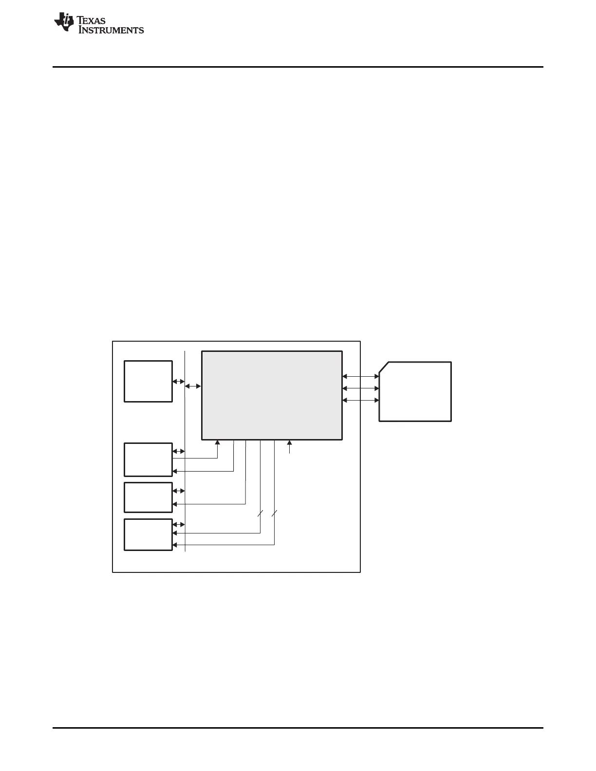
In 3-pin mode, only one SPI device can be on the bus (see Figure 8-13).
Figure 8-13. 3-Pin Mode System Overview
In 3-pin mode, not all options related to chip-select management are used:
• MCSPI_CHxCONF[EPOL]
• MCSPI_CHxCONF[TCS0]
• MCSPI_CHxCONF[FORCE]
The chip-select pin SPIEN is forced to 0 in this mode.
8.2.4 Slave Mode
The SPI is in slave mode when the MS bit of the SPI_MODULCTRL register is set. In slave mode, the SPI
should be connected to only one external master device.