1400 Keysight InfiniiVision 4000 X-Series Oscilloscopes Programmer's Guide
36 :WAVeform Commands
If there is a hole in the data, the hole is represented by a value of 0. The
BYTE-formatted data transfers over the programming interface faster than
ASCii or WORD-formatted data, because in ASCii format, as many as 13 bytes
per point are transferred, in BYTE format one byte per point is transferred, and
in WORD format two bytes per point are transferred.
The :WAVeform:BYTeorder command (see page 1401) has no effect when the
data format is BYTE.
Digital Channel Data (MSO models only)
The waveform record for digital channels is similar to that of analog channels. The
main difference is that the data points represent either DIGital0,..,7 (POD1),
DIGital8,..,15 (POD2), or any grouping of digital channels (BUS1 or BUS2).
For digital channels, :WAVeform:UNSigned (see page 1423) must be set to ON.
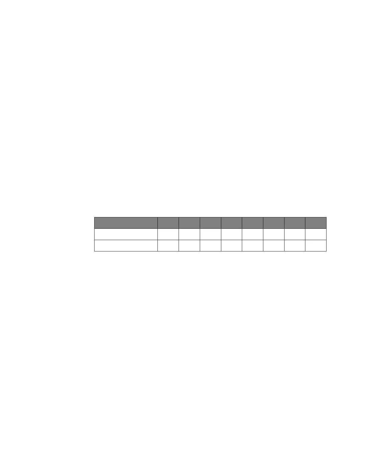
Digital Channel POD Data Format
Data for digital channels is only available in groups of 8 bits (Pod1 = D0 - D7, Pod2
= D8 - D15). The bytes are organized as:
If the :WAVeform:FORMat is WORD (see page 1405) is WORD, every other data
byte will be 0. The setting of :WAVeform:BYTeorder (see page 1401) controls
which byte is 0.
If a digital channel is not displayed, its bit value in the pod data byte is not defined.
Digital Channel BUS Data Format
Digital channel BUS definitions can include any or all of the digital channels.
Therefore, data is always returned as 16-bit values. :BUS commands (see
page 321) are used to select the digital channels for a bus.
Reporting the Setup
The following is a sample response from the :WAVeform? query. In this case, the
query was issued following a *RST command.
:WAV:UNS 1;VIEW MAIN;BYT MSBF;FORM BYTE;POIN +1000;SOUR CHAN1;SOUR:SUBS
NONE
:WAVeform:SOURce Bit 7 Bit 6 Bit 5 Bit 4 Bit 3 Bit 2 Bit 1 Bit 0
POD1 D7 D6 D5 D4 D3 D2 D1 D0
POD2 D15 D14 D13 D12 D11 D10 D9 D8

 Loading...