System Status and Configuration Module (SSCM)
MPC5606S Microcontroller Reference Manual, Rev. 7
1214 Freescale Semiconductor
• Debug Status Port enable and selection
• Bus and peripheral abort enable/disable
38.1.3 Modes of operation
The SSCM operates identically in all system modes.
38.2 Memory map and register description
This section provides a detailed description of all memory-mapped registers in the SSCM.
38.2.1 Memory map
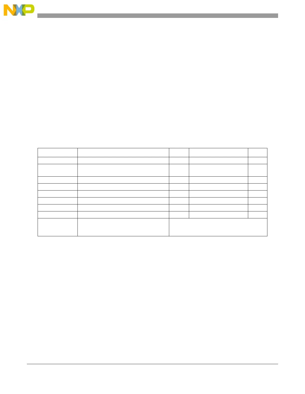
Table 38-1 shows the memory map for the SSCM. Note that all addresses are offsets; the absolute address
may be calculated by adding the specified offset to the base address of the SSCM.
All registers are accessible via 8-bit, 16-bit or 32-bit accesses. However, 16-bit accesses must be aligned
to 16-bit boundaries, and 32-bit accesses must be aligned to 32-bit boundaries. As an example, the
STATUS register is accessible by a 16-bit READ/WRITE to address ‘Base + 0x0002’, but performing a
16-bit access to
‘Base + 0x0003’ is illegal.
38.2.2 Register description
The following memory-mapped registers are available in the SSCM. Those bits that are shaded out are
reserved for future use. To optimize future compatibility, these bits should be masked out during any
read/write operations to avoid conflict with future revisions.
Table 38-1. module memory map
Address Register Size Access mode
1
1
U = User mode, S = Supervisor mode, T = Test mode, V = DFV mode, A = All (No restrictions)
Base + 0x0000 System Status (STATUS) 16-bit R A
Base + 0x0002 System Memory Configuration
(MEMCONFIG)
16-bit R A
Base + 0x0004 Reserved 16-bit Reads/writes have no effect A
Base + 0x0006 Error Configuration (ERROR) 16-bit R/W A
Base + 0x0008 Debug Status Port (DEBUGPORT) 16-bit R/W A
Base + 0x000A Reserved 16-bit Reads/writes have no effect A
Base + 0x000C Password Comparison Register High Word 32-bit R/W A
Base + 0x0010 Password Comparison Register Low Word 32-bit R/W A
Base + 0x0014
to
Base + 0x3FFF
Reserved See Note
2
2
If enabled at the SoC level, accessing these register addresses will cause bus aborts.

 Loading...


