Flash Memory
MPC5606S Microcontroller Reference Manual, Rev. 7
554 Freescale Semiconductor
If the flash memory module enters Low-Power mode during an erase operation, the MCR[ESUS] bit is set.
The user may resume the erase operation when the module exits Low-Power mode by clearing the
MCR[ESUS] bit. The MCR[EHV] bit must be high to resume the erase operation.
If the flash memory module is configured to enter Low-Power mode during a program operation, the
operation will be completed and the Low-Power mode will be entered only after the programming ends.
It is forbidden to enter Power-Down mode when the Low-Power mode is active.
17.2.6 Register description
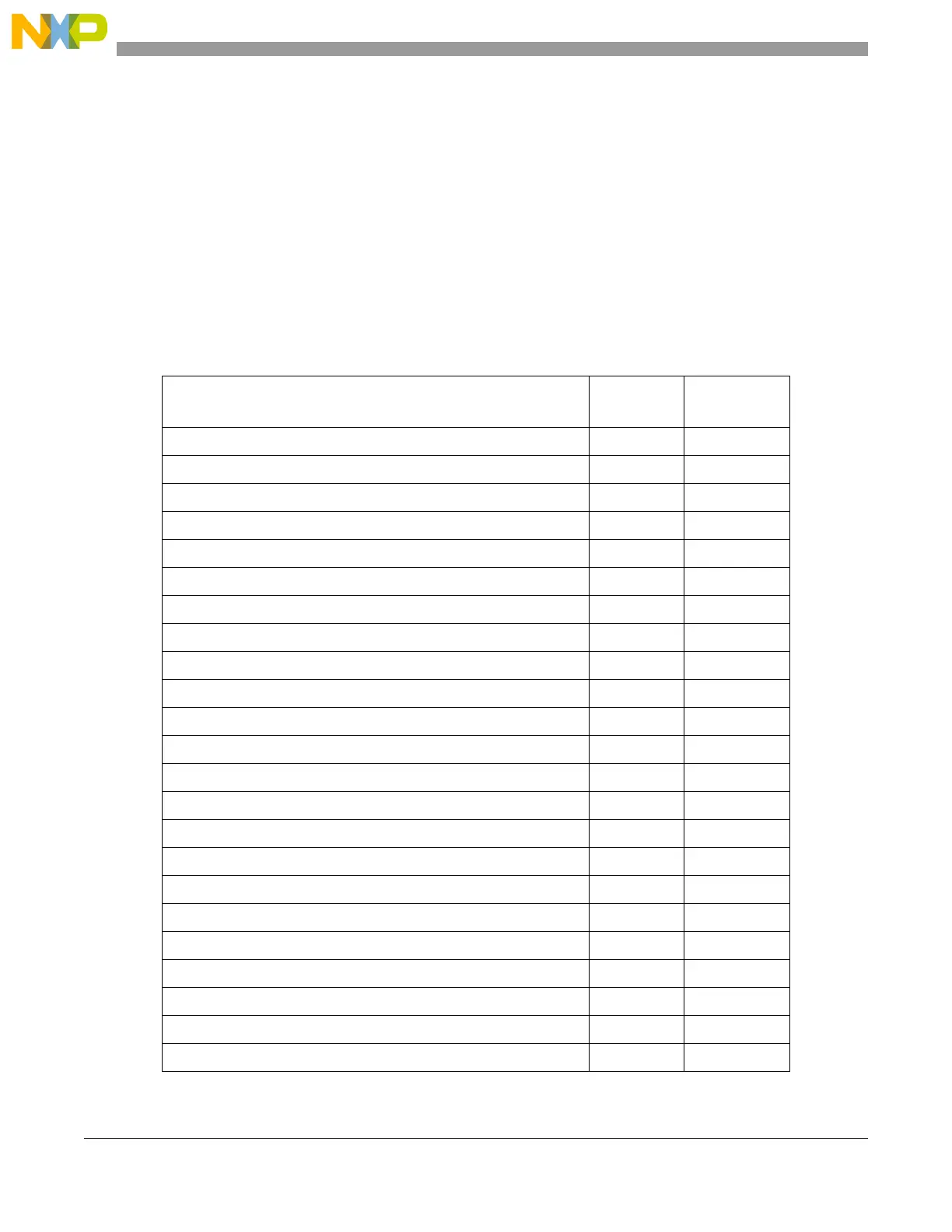
The flash memory user registers mapping is shown in Table 17-6.
Table 17-6. Flash 528 KB single bank registers
Register name
Address
Offset
Location
Module Configuration Register (MCR) 0x0000 on page 555
Low/mid Address Space Block Locking Register (LML) 0x0004 on page 560
High Address Space Block Locking Register (HBL) 0x0008 on page 563
Secondary Low/mid Address Space Block Lock Register (SLL) 0x000C on page 564
Low/mid Address Space Block Select Register (LMS) 0x0010 on page 567
High Address Space Block Select Register (HBS) 0x0014 on page 568
Address Register (ADR) 0x0018 on page 569
Bus Interface Unit Register 0 (BIU0) 0x001C on page 571
Bus Interface Unit Register 1 (BIU1) 0x0020 on page 571
Bus Interface Unit Register 2 (BIU2) 0x0024 on page 572
Reserved 0x0028
Reserved 0x002C
Reserved 0x0030
Reserved 0x0034
Reserved 0x0038
User Test Register 0 (UT0) 0x003C on page 573
User Test Register 1 (UT1) 0x0040 on page 575
User Test Register 2 (UT2) 0x0044 on page 576
User Multiple Input Signature Register 0 (UMISR0) 0x0048 on page 576
User Multiple Input Signature Register 1 (UMISR1) 0x004C on page 577
User Multiple Input Signature Register 2 (UMISR2) 0x0050 on page 578
User Multiple Input Signature Register 3 (UMISR3) 0x0054 on page 578
User Multiple Input Signature Register 4 (UMISR4) 0x0058 on page 579

 Loading...


