Display Control Unit (DCU)
MPC5606S Microcontroller Reference Manual, Rev. 7
420 Freescale Semiconductor
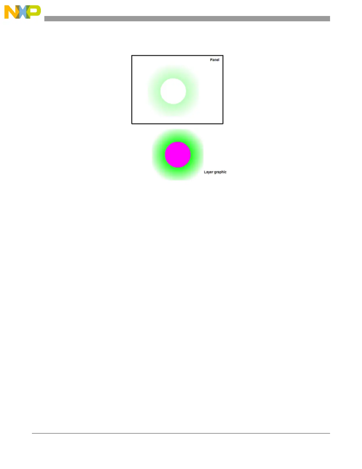
Figure 12-68. Case 14 example (selected pixels removed, pixel and layer alpha used in blend)
12.4.5.6 Transparency mode and blending
Transparency mode is a special case for the graphic data format and is defined by the BPP bit field in
register 4 in the control descriptor for the layer (CTRLDESCLn_4, where n is the layer number). This
value also influences the range of values for the width of the layer (see Section 12.4.5.3, Layer size and
positioning). By choosing an appropriate format, it is possible to optimize the memory required by the
graphics in use.
In transparency mode, the source graphic does not contain any direct or indexed color information. Instead,
the graphic data represents the alpha channel of the graphic. The DCU creates the final graphic by
pre-blending a foreground color and background color using the alpha value of each pixel. The result of
this pre-blend can then be blended with pixels on other layers using the normal blending process. Each
layer has dedicated registers to contain the foreground and background colors for this mode. These are
FGn_fcolor and FGn_bcolor, where n is the layer number.
Transparency mode is typically used when a graphic must blend smoothly into the underlying layers, but
where a rich color palette is not required. Examples include text where this mode allows the text to blend
smoothly with any background — this is known as anti-aliasing.
There are two transparency modes available: 4 bpp and 8 bpp. The result of the pre-blend can be treated
as an RGB888 graphic and blended in a similar way to previously described, or it can be treated as a special
case of ARGB with only the foreground color visible in the final blend.
Table 12-62 describes the blend
options for transparency mode.

 Loading...


