Stepper Motor Controller (SMC)
MPC5606S Microcontroller Reference Manual, Rev. 7
Freescale Semiconductor 1129
NOTE
The SMC will release the pins after the next PWM timer counter overflow
without accommodating any channel delay if a single channel has been
disabled or if the period register has been cleared or all channels have been
disabled. Program one or more inactive PWM frames (duty cycle = 0)
before writing a configuration that disables a single channel or the entire
SMC.
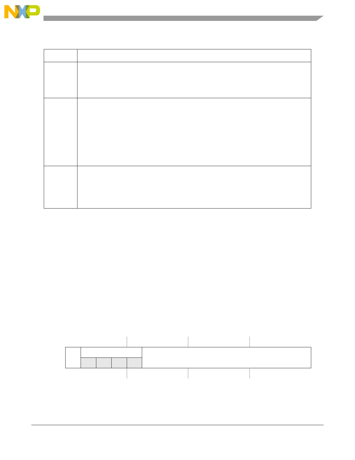
35.3.2.5 Motor Controller Duty Cycle Register (MCDC0..11)
Each duty cycle register sets the sign and duty functionality for the respective PWM channel. The number
of each register refires directly the PWM channel it controls. The relation between channels, pin names
and register names is shown in Table 35-19.
Table 35-7. MCCCx field descriptions
Field Description
MCOM Output Mode — MCOM controls the PWM channel’s output mode.
00 Half H-bridge mode, PWM on pin MnCxM, pin MnCxP is released
01 Half H-bridge mode, PWM on pin MnCxP, pin MnCxM is released
10 Full H-bridge mode
11 Dual full H-bridge mode
MCAM PWM Channel Alignment Mode — MCAM controls the PWM channel’s PWM alignment mode and
operation.
MCAM and MCOM are double buffered. The values used for the generation of the output waveform
will be copied to the working registers either at once (if all PWM channels are disabled or
MCPER[PER] is set to 0) or if a timer counter overflow occurs. Reads of the register return the most
recent written value, which are not necessarily the currently active values.
00 Channel disabled
01 Left aligned
10 Right aligned
11 Center aligned
CD PWM Channel Delay — Each PWM channel can be individually delayed by a programmable number
of PWM timer counter clocks. The delay will be n/f
TC
.
00 Zero PWM clocks channel delay
01 One PWM clock channel delay
10 Two PWM clocks channel delay
11 Three PWM clocks channel delay
Offset Module Base + 0x0020 . . . 0x0037
0 1 2 3 4 5 6 7 8 9 10 11 12 13 14 15
R
SIGN
[4]
SIGN[3:0]
DUTY
W
Reset 0 0 0 0 0 0 0 0 0 0 0 0 0 0 0 0
Figure 35-6. Motor Controller Duty Cycle Register (MCDC0..11)
 Loading...