LCD Driver (LCD64F6B)
MPC5606S Microcontroller Reference Manual, Rev. 7
Freescale Semiconductor 813
• The LCD64F6B system is configured in the default mode, 1/1 duty and 1/1 bias, that means only
BP0 is used, system clock as reference, VLCD pin not used as voltage reference.
22.5.2 LCD clock and frame frequency
The frequency of the clock and the clock divider determine the LCD Clock Frequency. The input clock for
the prescaler can be selected by LCDRCS bit. The divider is set by the LCD Clock Prescaler bits, in the
LCD Prescaler Control Register according to Table 22-27.
The following formula may be used to calculate the LCD frame frequency:
Eqn. 22-1
Example: Clock = 16 MHz, Prescaler = 1010;
Eqn. 22-2
NOTE
A “Frame” is the full refresh cycle of the display. See Section 22.6, LCD
waveform examples, for waveform illustrations.
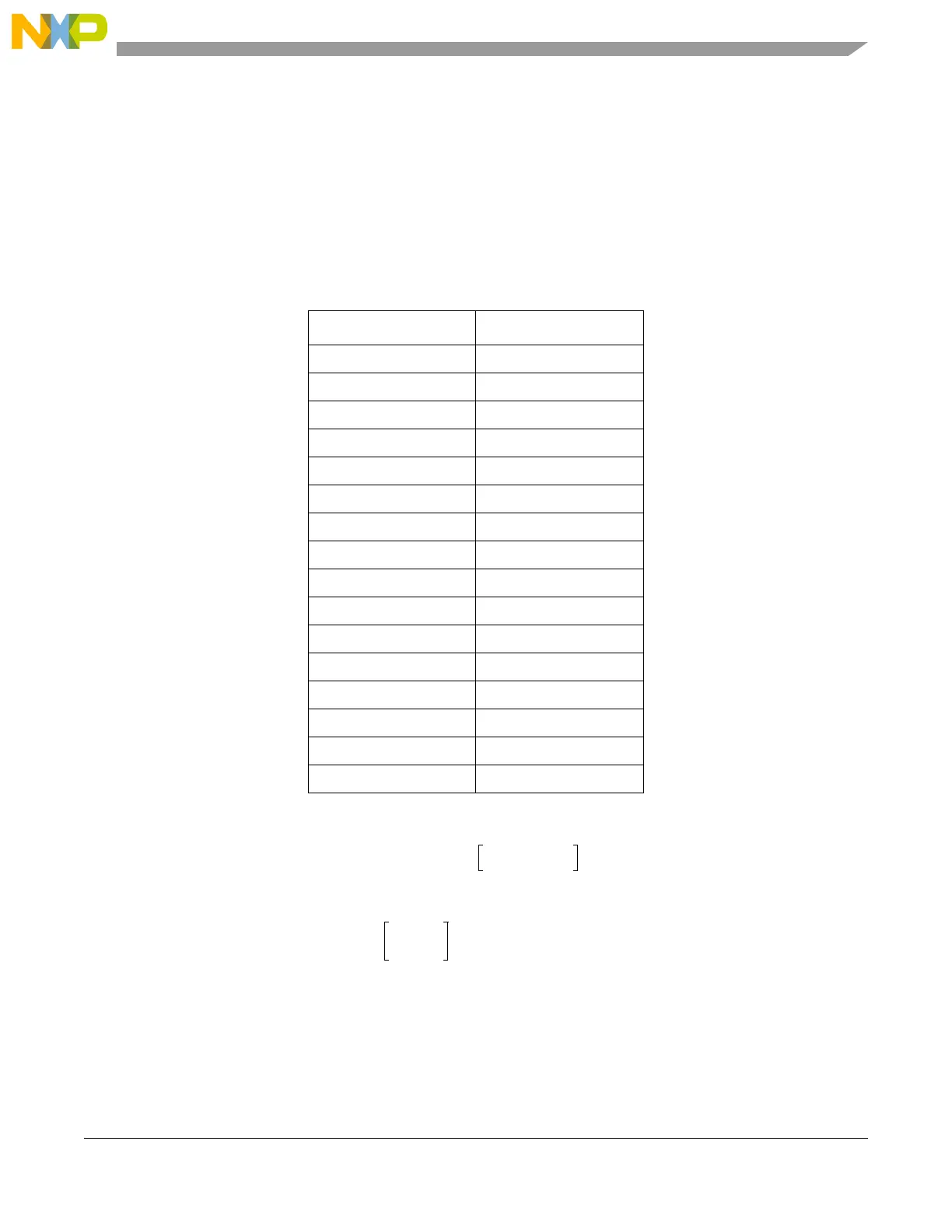
Table 22-27. Clock divider
LCLK Divider
0000 480
0001 2 * 480
0010 2
2
* 480
0011 2
3
* 480
0100 2
4
* 480
0101 2
5
* 480
0110 2
6
* 480
0111 2
7
* 480
1000 2
8
* 480
1001 2
9
* 480
1010 2
10
* 480
1011 2
11
* 480
1100 2
12
* 480
1101 2
13
* 480
1110 2
14
* 480
1111 2
15
* 480
LCD Frame Frequency (Hz)
OSCCLK Hz
Divider
--------------------------------------
=
16 10
6
2
10
480
----------------------
33 Hz

 Loading...


