LIN Controller (LINFlex)
MPC5606S Microcontroller Reference Manual, Rev. 7
874 Freescale Semiconductor
To fulfill this requirement, the LINFlex controller provides configurable filters in order to request software
intervention only if needed. This hardware filtering saves CPU resources that would otherwise be needed
by software for filtering.
23.8.2.3.1 Filter mode
Usually each of the eight IFCR registers filters one dedicated identifier, but this limits the number of
identifiers LINFlex can handle to the number of IFCR registers implemented in the device. Therefore, in
order to be able to handle more identifiers, the filters can be configured in mask mode.
In identifier list mode (the default mode), both filter registers are used as identifier registers. All bits of
the incoming identifier must match the bits specified in the filter register.
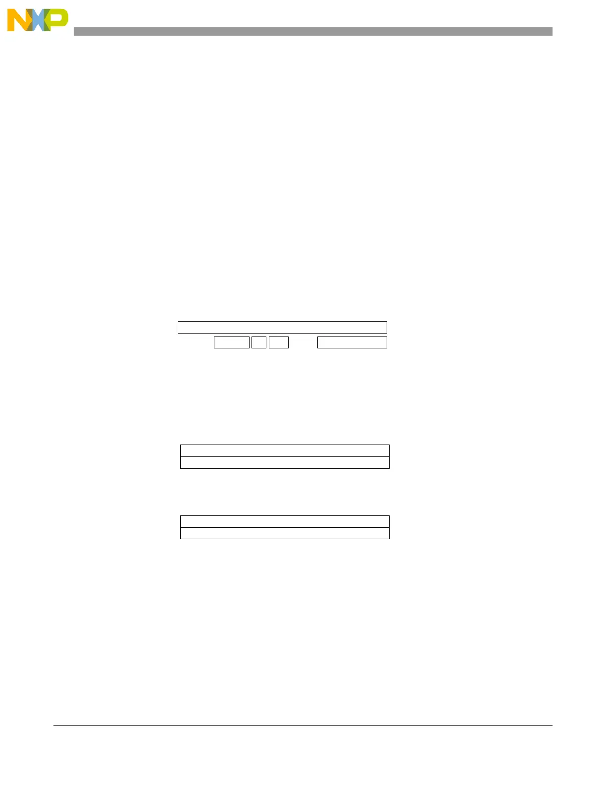
In mask mode, the identifier registers are associated with mask registers specifying which bits of the
identifier are handled as “must match” or as “don’t care”. For the bit mapping and registers organization,
please refer to Figure 23-30.
Figure 23-30. Filter configuration—register organization
23.8.2.3.2 Identifier filter mode configuration
The identifier filters are configured in the IFCRx registers. To configure an identifier filter the filter must
first be deactivated by clearing the FACT bit in the IFER. The identifier list or identifier mask mode for
the corresponding IFCRx registers is configured by the IFM bit in the IFMR. For each filter, the IFCRx
register configures the ID (or the mask), the direction (TX or RX), the data field length, and the checksum
type.
If no filter is active, an RX interrupt is generated on any received identifier event.
IFCRn
Identifier
ID
Bit Mapping
Identifier Filter Register Organization
15
0
DFL CCSDIR
Identifier Filter Configuration
IFCR2n
Identifier
Identifier
IFCR2n +1
IFM = 0
Identifier Filter Mode
IFCR2n
Identifier
Mask
IFCR2n +1
IFM = 1
Identifier List Mode
Mask Mode
[0:2] [0:5]

 Loading...


