Scan Edge WidthFH/FZ5 Processing Item Function Reference Manual
265
2
Inspecting and Measuring
Key Points for Test Measurement and Adjustment (Scan Edge Width)
The following contents can be displayed as text in the "Detail result" area.
The image specified in the Sub-image number in image display setting is displayed in the Image Display area.
Key Points for Adjustment
Select the adjustment method referring to the following points.
When the measurement results are unstable
Measurement Results for Which Output Is Possible (Scan Edge Width)
The following values can be output using processing items related to results output. It is also possible to
reference measurement values from expressions and other processing units.
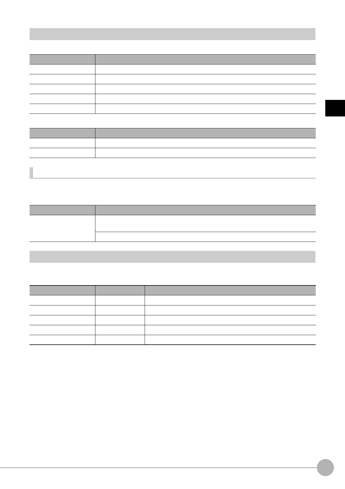
Displayed items Description
Judge Judgement result
Edge width Max. The maximum value of edge width
Edge width Min. The minimum value of edge width
Edge width Ave. The average value of all the edge width
Lost width count The number of the scanned areas for which the detectio
n of width failed
Sub image number Explanation of image to be displayed
0 Measurement image
1 Scan region
Parameter to be adjusted Remedy
Measurement
If the color of the edges to be detected is decided, specify the co
lor with [Edge color]. If results
are not stable even with the color specified, specify a larger value for the color variance range.
If noise is detected as an edge, specify larger valu
es
for "Noise level" and "Noise width".
Measurement items Character string Description
Judge JG Judgement result
Edge width Max. MAXW The maximum value of edge width
Edge width Min. MINW The minimum value of edge width
Edge width Ave. AVEW The average value of all the edge width
Lost width count LOST The number of the scanned areas for which the detection of width failed

 Loading...


