DefectFH/FZ5 Processing Item Function Reference Manual
361
2
Inspecting and Measuring
Measurement Parameters (Defect)
This item specifies the judgement condition for measurement results. Measurement parameters can be changed
as needed to address unstable measurement results or to increase the processing speed.
1 In the Item Tab area, click [Measurement].
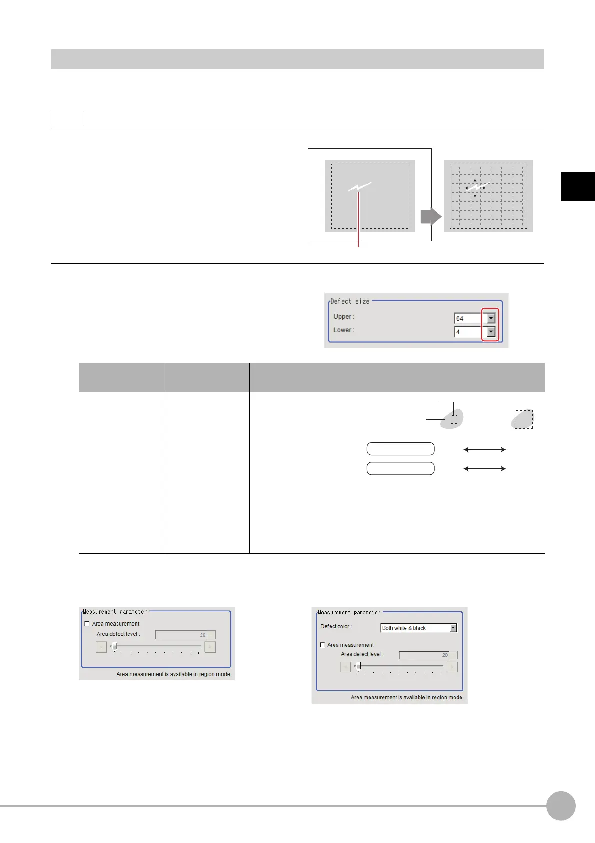
2 Set the value of each item in the "Defect
size" area.
3 If necessary, set the value of each item in the "Measurement parameter" area.
Defect detection mechanism
• After measurement region is drawn, a rectangle (defect
dete
ction region) is automatically formed in this region.
While moving the defect detection region around,
calculate the RGB color averages at each location and
find the defect detection difference with surrounding
defects. This difference is called the defect level.
Calculate the defect level for all defect detection areas. If
the maximum value exceeds the judgement value, it is
judged that there are defects in the measurement region.
Setting item
Set value
[Factory default]
Description
Defect size
•4
•8
•12
•16
•24
•32
•64
[4] to [64]
Specify the upper and
lowe
r li
mits of defect
detection size based on
the size of scratch or
contamination to be
detected. A defect
detection region is
automatically created
with the number of pixels for the defects size.
The larger the difference between upper and lower limits, the easier to
detect
d
efects/contamination of various sizes.
For both upper and lower limits, higher values for defect detection size
limit
s
leads to weaker detection sensitivity and shorter processing time.
For color cameras: For monochrome cameras:
Defect detection region
Defect
Sensitivity high low
Defect detection
size
Defect
Processing Time
long short

 Loading...


