Circular Scan Edge PositionFH/FZ5 Processing Item Function Reference Manual
273
2
Inspecting and Measuring
3 In the scene in the "Unit" area, select a
detection point unit.
4 Perform the next measurement, and the reference will be displayed.
Measurement Parameters (Circular Scan Edge Position)
Measurement parameters can be changed as needed to address unstable measurement results. Normally, the
factory default value will be used.
After changing a setting, check wheth
e
r measurement can be done properly by performing an actual
measurement.
1 In the Item Tab area, click
[Measurement].
The edge profile of the measurement region is
displayed as a graph in the Image Display
area.
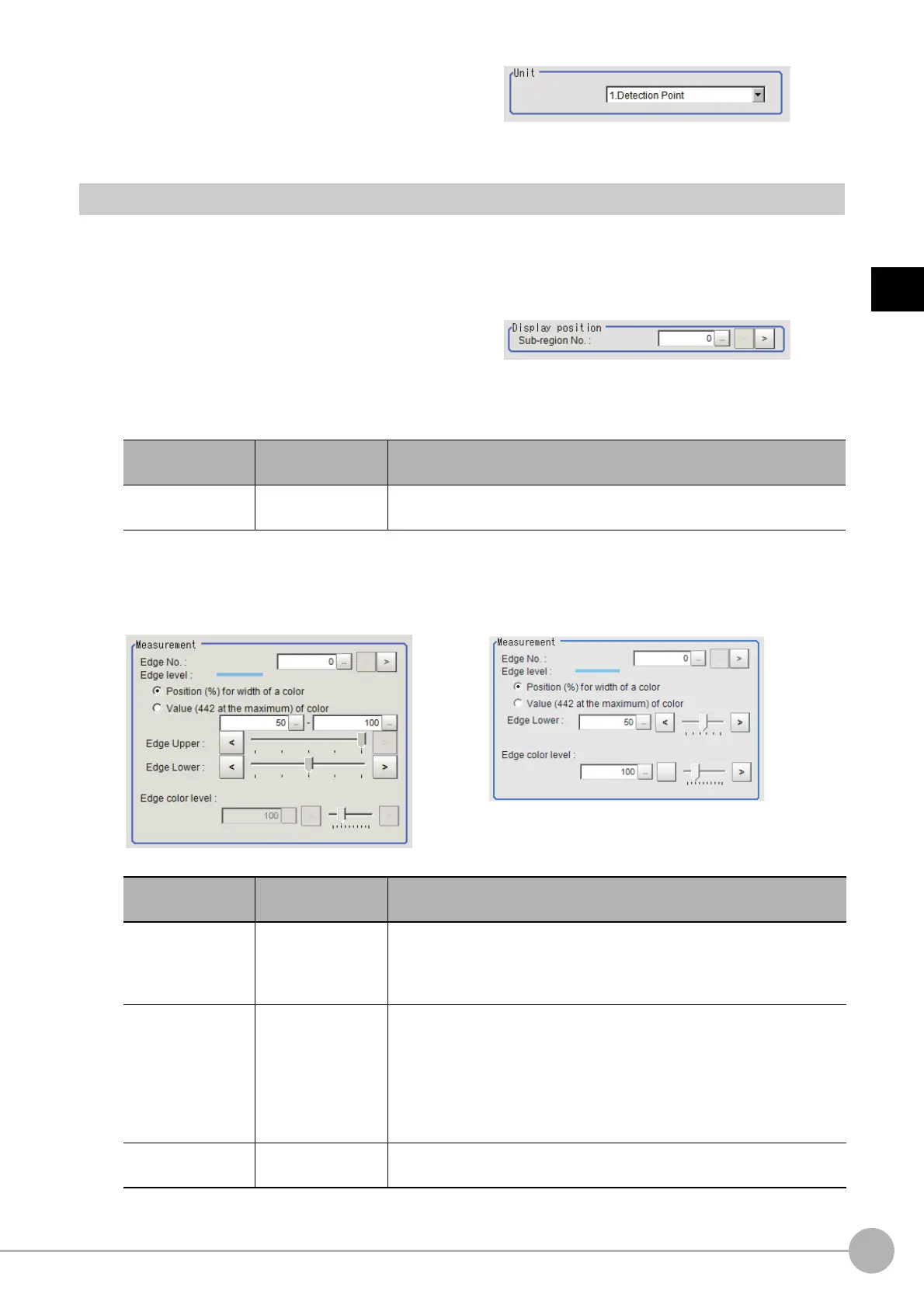
2 Set the value of each item in the "Measurement" area.
For color cameras:
Setting item
Set value
[Factory default]
Description
Sub-region No.
0 to 359
[0]
Specify the edge measurement number for
which the edge profile is
displayed.
Edge Color Not Specified Edge Color Specified
Setting item
Set value
[Factory default]
Description
Edge No.
0 to 99
[0]
Specify the edge number used to extract edges.
Edge numbers are assigned to detected edges starting from 0 and in the
directio
n from the st
art point (the arrow) to the end point (the arrow point)
in the selected region.
Edge Upper (only
whe
n edge color is
not specified)
Edge Lower
• Position (%) for
wid
th of a color
0 to 100
[50] to [100]
• Value of color
0 to 442
[20] to [442]
Set a range of a color difference level with whi
ch the edge is detected.
Reference: "Appendixes Measurement Mechanism Edge Detection
Measuremen
t" in the "Vision System FH/FZ5 Series User's Manual
(Z365)"
Edge color level
0 to 442
[100]
This emphasis level can be set only if the edge color to detect is specified.

 Loading...


