DefectFH/FZ5 Processing Item Function Reference Manual
363
2
Inspecting and Measuring
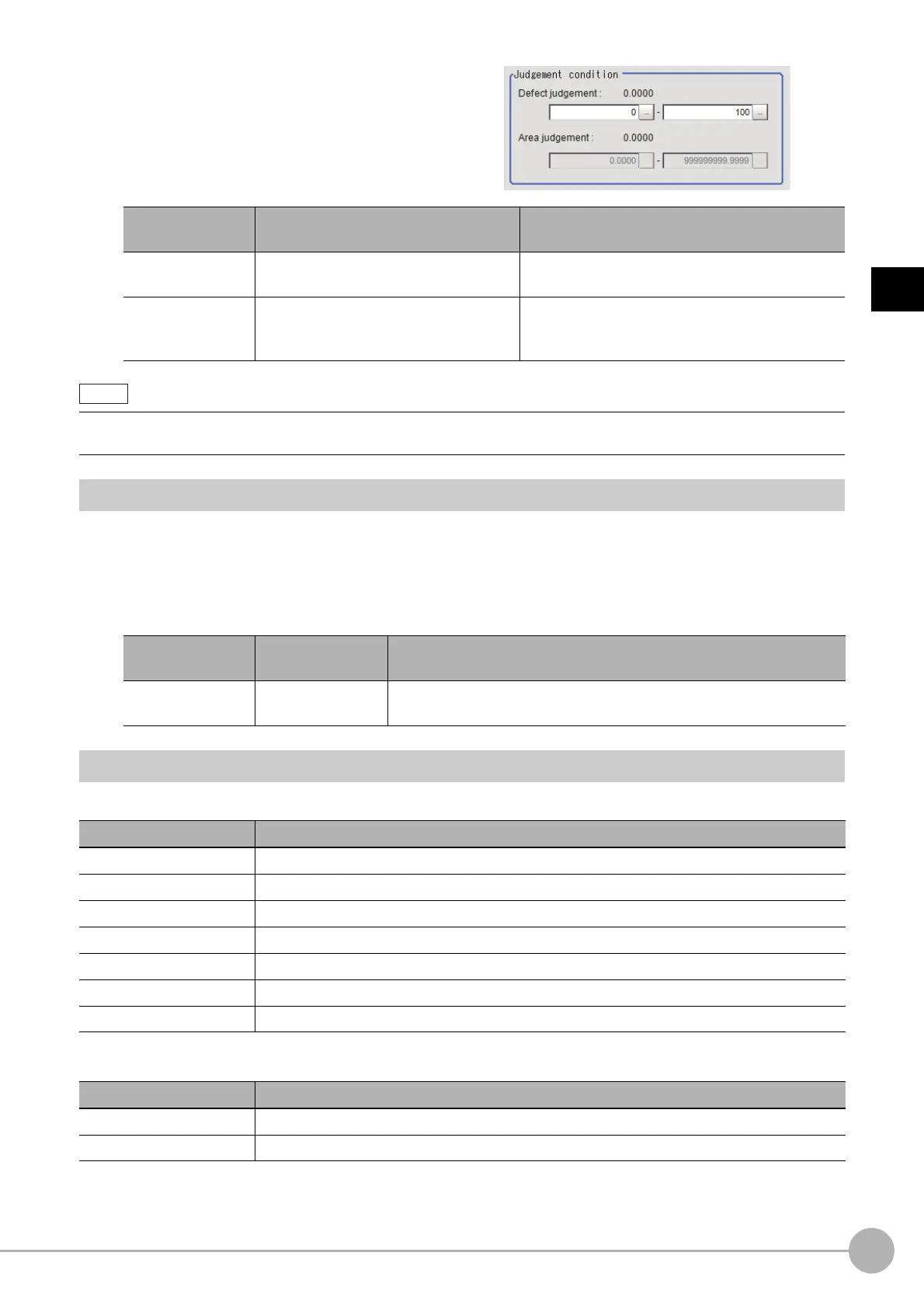
5 Set up the judgement condition.
Output Parameters (Defect)
Specifies whether or not the judgement results of this processing unit is reflected in the scene overall judgement.
1 Click [Output parameter] in the Item Tab area.
2 Choose whether or not to reflect this in the scene overall judgement in "Reflect to overall
judgement" area.
Key Points for Test Measurement and Adjustment (Defect)
In the "Detail result" area on the Main screen, you can confirm the following contents in text.
The image specified in the Sub-image number in image display setting is displayed in the Image Display area.
Item
Set value
[Factory default]
Description
Defect judgement
0 to 999
[0] to [100]
Specify the range of defect judgement values that
are judged to be OK.
Area judgement
0 to 307200 (for a 0.3-megapixel camera)
0 to 1920000 (for a 2-megapixel camera)
0 to 4320000 (for a 5-megapixel camera)
Specify the range of area jud
gemen
t values that are
judged to be OK.
• The values beside each item are measurement results of the displayed image. Take these values into consideration to
determine the upper and lower limit values.
Setting item
Set value
[Factory default]
Description
Reflect to overall
judgemen
t
•[ON]
•OFF
Enables choosing whether or not the judgement results of this processing
unit is reflected in the scene overall judgement.
Displayed items Description
Judge Judgement result
Defect Measured defect level
Position X X Coordinate of measured defect position
Position Y Y coordinate of measured defect position
Area The measured maximum defect area
Gravity X The center of gravity X coordinates of
the
measured maximum defect area
Gravity Y The center of gravity Y coordinates of the
measured maximum defect area
Sub image number. Explanation of image to be displayed
0 Measurement image
1 Defect profile [when area measurement is present]

 Loading...


