Camera Image Input FHFH/FZ5 Processing Item Function Reference Manual
53
1
Input image
Assigning Multiple Electronic Flashes to a Camera
It is possible to assign multiple electronic flashes (STGOUT signals) to a camera and select one to use when an
image is taken for measurement. This function uses STGOUT signals with which cameras are not connected.
This function can be used only with FH series Sensor Controller.
Follow the setting procedure below.
1 Click [Tool] - [System settings] - [Camera] - [Output signal setting].
Reference: Setting the SHTOUT Signal: [Output Signal Settings] in the Vision System FH/FZ5 Series
User's Manual (Cat. No. Z365).
2 Select [STGOUT] for [Output Signal] in "Common setting" area.
3 Place a check to [Output even if camera is not connected] in "STGOUT setting" area.
With this setting, STGOUT signals (STGOUT0 to STGOUT7) which are not connected with cameras can
be used. Configure the STGOUT Width of the STGOUT of corresponding Camera Image Input FH
Processing Item.
Reference: Electronic Flash Setting of the Vision System FH/FZ5 Series Processing Item Function
Re
fer
ence Manual (Cat No. Z341).
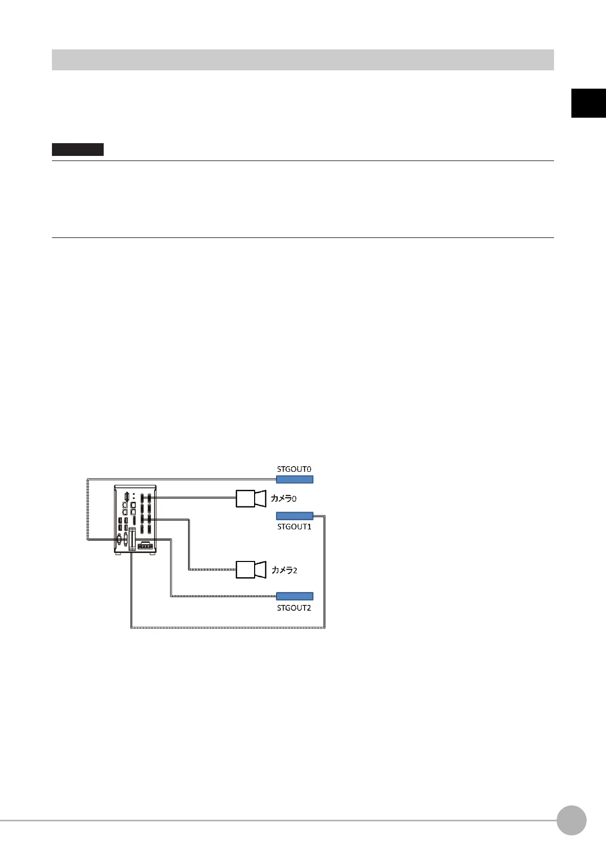
Example:
Camera 0 uses STGOUT0 and STGOUT1 and Camera 2 uses STGOUT2.
4 To use STGOUT0 and STGOUT1 for Camera 0, Camera 1 is not connected with a camera.
5 In the [Electronic flash setting] area in the Camera 0 tab of Camera Image Input FH
processing item, enter the settings for SGTOUT 0.
6 In the [Electronic flash setting] area in the Camera 1 tab of Camera Image Input FH
processing item, enter the settings for SGTOUT 1.
7 In the [Electronic flash setting] area in the Camera 2 tab of Camera Image Input FH
processing item, enter the settings for SGTOUT 2.
8 In the [Electronic flash setting] area in the Camera 3 to 7 tab of Camera Image Input FH
processing item, set 0 to the STGOUT width.
• The STGOUT signals that can be output are as follows.
: FH-1000 and FH-3000 series: SGTOUT 0 to 7
: FH-L series: STGOUT 0 to 3
• STGOUT0 to STGOUT7 is tied to the camera connector number of the se
nsor con
troller, not the camera number. When
you use CameraLink Medium Configuration or the Multi-line random-trigger mode, confirm the camera connector
number that corresponds to the camera number of Sensor Controller.

 Loading...


