Fine Matching
382
FH/FZ5 Processing Item Function Reference Manual
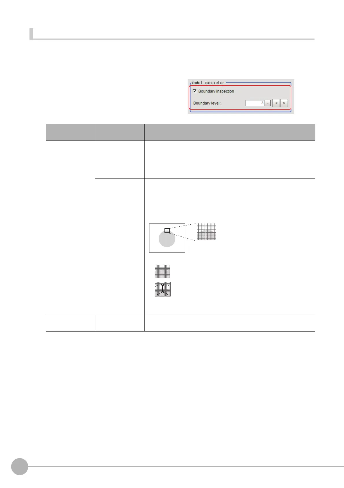
Changing Model Parameters
The range can be changed as needed to address unstable measurement results. Normally, the factory default
value will be used.
After changing a setting, check wheth
e
r measurement can be done properly by performing an actual
measurement.
1 In the "Model parameter" area, specify a
value for each item.
Setting item
Set value
[Factory default]
Description
Boundary
insp
ection
[Checked]
Defects around boundaries with color cha
nge
s can also be detected. The
edges similar to those in the model image are not regarded as defects.
Check this option when inspecting defects around boundaries, such as
chips and burrs. Defects along a direction different from the model image
profile are detected in the range of pixels of profile ± boundary level.
Unchecked
Boundary areas are excluded from the in
spection. This can prevent
matching mistakes due to positional deviation of measurement objects,
but defects around boundaries cannot be detected.
"Boundary level" can be used to specify how many pixels around
bou
ndaries should be excluded from the inspection.
Boundary level
0 to 9
[3]
Select the degree of assimilation of variations around boundaries.
Depending on the "Boundary inspection" value, the meaning is different.
If the measurement object moves up slightly,
its difference with the model will be detected as the edge part.
(1 grid = 1 pixel)
Model
Measurement image
When setting Edge Measurement to “Disabled”, the range of
the “Model edge ± Boundary level” will be outside of the
measurement object.
Example) When “Edge level” is 3, the range with a width of
6 pixels will not be outside of the measurement object.

 Loading...


