Scan Edge Position
250
FH/FZ5 Processing Item Function Reference Manual
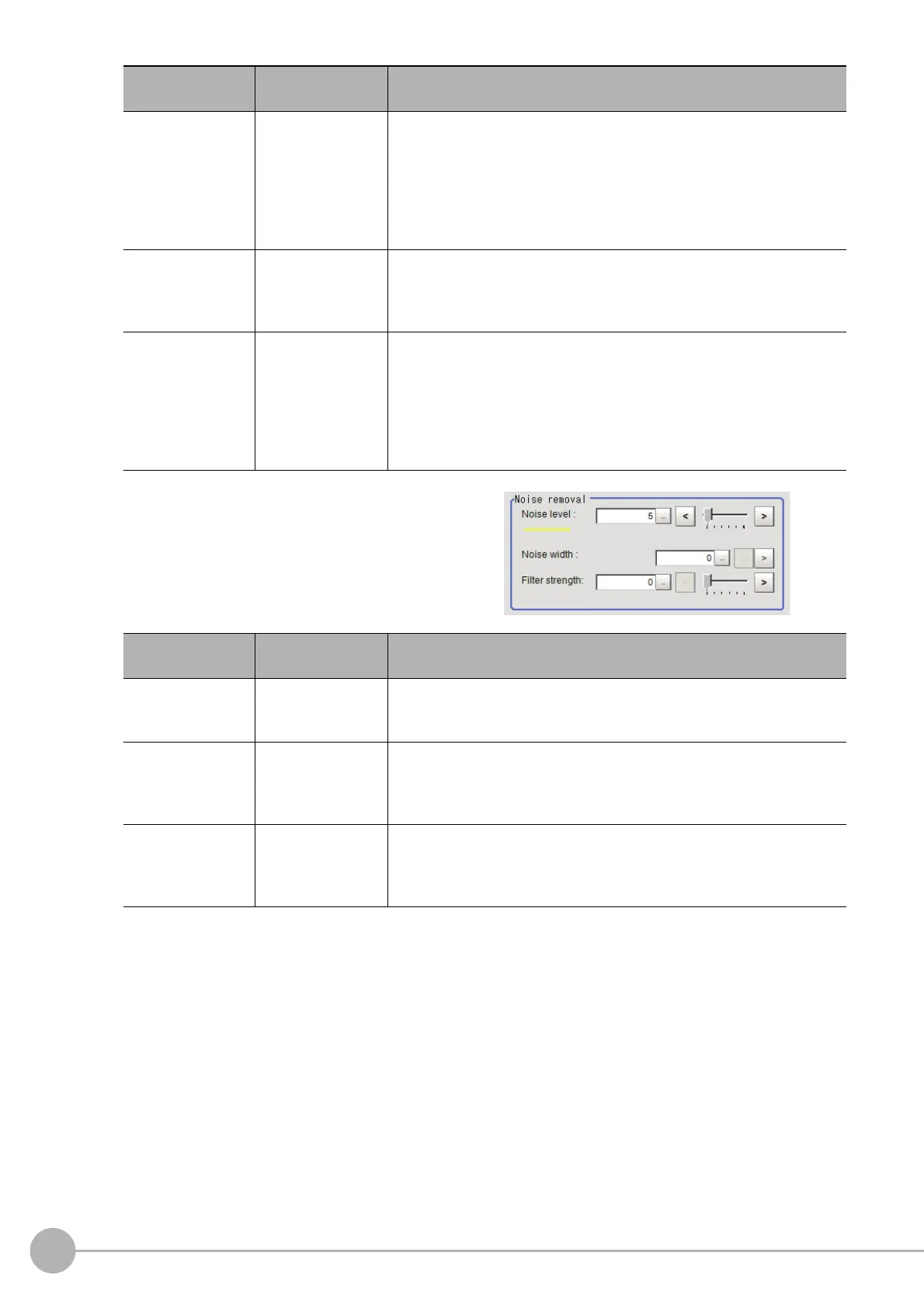
4 If necessary, set each item in the "Noise
removal" area.
Density change
• Absolute
(only when the
measur
ement
method is
"Derivation")
•[Light→Da
rk]
•D
ark→Light
Select whe
ther a black-to-white change or a white-to-black change should
be recog
nized as a density change in the specified region.
Edge No.
0 to 99
[0]
Specify the edge number used to extract edges.
Edge numbers are assigned to detected edges starting from 0 and going
on in the di
re
ction from the start point (the arrow point) to the end point
(the direction of arrow) in the selected area.
Edge Upper
Edge Lower
• Position (%) for
wid
th
of a density
0 to 100
[50] to [100]
• Value of density
0 to 255
[20] to [255]
Select the density change level to be detected as edges.
The upper limit of edges can be set only when the measurement method
is "Derivatio
n".
Reference: "Appendixes Measurement Mechanism Edge Detection
Measureme
n
t" in the "Vision System FH/FZ5 Series User's Manual
(Z365)"
Setting item
Set value
[Factory default]
Description
Noise level
0 to 442
[5]
When detection is affected by noise, increase this value.
Reference: "Appendixes Measurement Mechanism Noise Level" in the
"V
isi
on System FH/FZ5 Series User's Manual (Z365)"
Noise width
0 to 9999
[0]
Set the width for judging noise.
When detection is affected by noise, increase this value.
Reference: "Appendixes Measurement Mechanism Noise Width" in
th
e "V
ision System FH/FZ5 Series User's Manual (Z365)"
Filter strength
0 to 100
[0]
If a valley appears in the histogram ar
ound the edge threshold value due
to noises, smoothen the edge profile using a filter to prevent wrong error
detection from being detected.
Strengthening the filter smoothen the edge profile further.
Setting item
Set value
[Factory default]
Description

 Loading...


