Precise CalibrationFH/FZ5 Processing Item Function Reference Manual
641
4
Support Inspection and Measurement
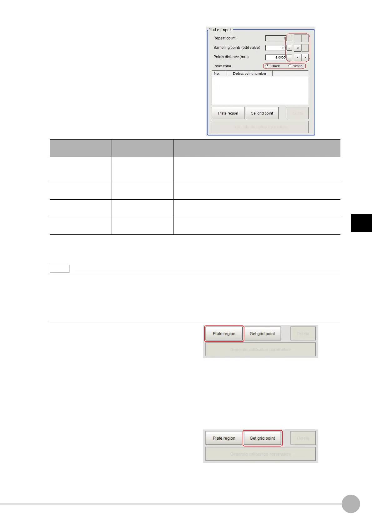
4 Shoot the pattern plate and set each
item.
5 Set the plate region as necessary.
The default value setting is for the entire screen.
Click [Plate region].
Use the drawing tools to specify the pattern plate range.
Click [OK] in the Figure setting area.
• [OK]: Changes the settings and returns to the previous menu.
• [Cancel]: Changes are discarded. R
eturns to the previous menu.
• [Apply]: Updates the settings without leaving edit window.
The pattern plate range is registered.
6 Click [Get grid point].
The grid points gotten are listed in the Plate
input area.
Setting item
Set value
[Factory default]
Description
Repeat count
1 to 10
[1]
Shooting the plate multiple times enables detection with grid
po
ints stabilized even for images with high noise levels. Set the
number of repetitions.
Sampling points
1.0000 to 1000.0000
[5.0000]
Set the point string count for the pattern plate.
Points distance
1 to 1000
[5]
Set the point interval for the pattern plate. The unit is in millimeters
(mm).
Point color
• [Black]
•White
Set the color of the circle marks on the pattern plate.
• Grid point extraction may fail if anything other than the p
a
ttern plate appears in the image. Specify the plate
region in this case.
• Grid point extraction may fail if a circle mark on the
p
attern plate appears incomplete or unclear. Exclude the
problem circle mark from the plate region in this case.
• Grid point extraction may fail if the brightness difference be
twe
en white and black regions on the pattern plate is
small, or if there is variation in brightness. Adjust the lighting or camera settings in this case.

 Loading...


